The quantification of large optics demands metrology systems that operate in the context of turbulence, vibration and additional challenges.
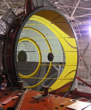
Figure 1. Measurement of large optics, such as this 8-meter primary mirror for the Large Binocular Telescope Observatory, requires metrology systems that can function despite vibration, turbulence and other challenges. (Courtesy R. Bertram and LBTO). Image Credit: 4D Technology
Introduction
The demand for meter-scale optical components has quickly grown in recent years, driven by an increase in satellite-based and terrestrial astronomy, and security and defense applications.
Laser interferometry is utilized across the manufacturing of large optics to validate adherence to stringent design requirements. ‘Dynamic interferometry’ has more recently been utilized for the vibration-resistant quantification of large optics.
The data is employed to manage polishing operations, validate the dimensional stability of support structures, line up mirror segments and perform other crucial metrology applications.
Requirements for Meter-Class Metrology
“Meter-class” denotes a variety of telescopes with optical components that are larger than one meter in diameter, normally functioning within the infrared through visible spectra. The secondary and primary optics can be monolithic glass structures or may comprise several elements that can be actively aligned.
The size of mirrors is only restricted by the present manufacturing techniques. Currently, over a dozen telescopes are operating with primary mirrors that are larger than eight meters, and many more complex projects are being developed.
Advanced metrology systems have been produced to offer quality assurance during the process in order to assist new manufacturing techniques. Laser interferometry is the most widespread method for validating the surface quality of large optics.
A laser interferometer quantifies the phase difference between beams reflecting from a test optic and from a high-quality reference optic. In a standard, ‘temporal’ laser interferometer, the reference optic is translated in relation to the test surface in established steps, usually quarter-wavelength shifts.
The equipment collects a frame of phase data after every shift. The optical path difference (OPD) can be established from this phase data, and the surface shape can be extracted.
After each polishing iteration, the measurement data is compared until the desired shape is realized. Several challenges have made the use of laser interferometry more complex as the diameter of optics has grown.
Vibration can significantly impact the quality of measurements as the measurement times are on the order of hundreds of milliseconds. Secondly, to quantify the total optical surface, the interferometer needs to be located at a significant ‘standoff’ distance from the test piece, which in some examples can be tens of meters away.
The phase data can be strongly distorted by turbulence within such a large cavity. Airflow control and vibration isolation systems of this scale can be functionally impractical or restrictively expensive.
A further challenge emerges when analyzing space-based hardware within actual-use environments, at cryogenic temperatures and/or extremely low pressure. The challenging conditions, along with the significant vibration from support equipment, make such real-world testing virtually impossible with conventional interferometers.
Non-traditional components, for example aspheric optics or conformable mirrors, are relied upon by a number of modern designs. Yet another challenge is created for metrology systems when characterizing these new components.
Dynamic Interferometry
A ‘dynamic interferometer’ gathers all phase data at once, unlike a temporal interferometer, which gathers phase data frames over hundreds of milliseconds.
An efficient acquisition time (usually a few microseconds) allows dynamic interferometers to quantify in high noise surroundings which lack vibration isolation.
This greatly decreases the cost and increases the simplicity of the organization and promotes testing in challenging environments for example those encountered in cryogenic testing. Dynamic systems can additionally perform testing in the presence of strong air movement.
Turbulence produces relative phase errors between the data frames, making the data found through temporal measurements unusable or inaccurate. This frame-to-frame error is not observed in dynamic interferometers.
Averaging multiple dynamic measurements negates the influence of turbulence, leaving only the shape of the optic in the measurement information.
Measuring Large Concave Mirrors
Manufacturers of telescope mirrors, for example the Steward Observatory Mirror Lab, have developed methods for creating lightweight mirrors greater than eight meters in diameter.
The general curvature of the mirror is formed through spin casting during cooling. This significantly decreases the quantity of raw material needed, along with the amount of polishing required.
The interferometer should be located several stories above the mirror in order to measure large, concave mirrors.
The path length for our measurements is typically 20 meters, single pass. Even measuring in the middle of the night in an isolated test tower, with all air handlers off, vibration and turbulence limit the accuracy we can get with a temporal interferometer. With our dynamic system we’re almost immune to vibration, and we can quickly take enough measurements to average out the effects of turbulence. It saves a lot of time and gives us more accurate data.
Buddy Martin, The Project Scientist, Steward Labs
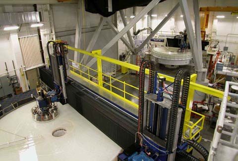
Figure 2. Dynamic interferometry data guides polishing of 8.4 meter and 6.4-meter mirrors. (Courtesy Steward Observatory Mirror Lab). Image Credit: 4D Technology
Testing Space Hardware in Actual Use Conditions
It is crucial to validate the ability of space-based optics to function to specification post-deployment, especially for systems intended to function beyond the reach of the Space Shuttle fleet.
The most successful way to verify that optical systems will function to specification is by testing them at low pressures and/or cryogenic temperatures. Cryo-vac testing takes place inside of a pressure vessel, which is a very noisy setting as a result of the vibration from its pumps.
Due to space limitations, it is challenging to couple the metrology system to the test sample and isolate them both from the vibration. When the test configuration demands a long measurement path, this proves to be impossible.
As dynamic interferometry is immune to vibration, manufacturers are freed from the limitation to couple the test optic and instrument.
This freedom promotes test configurations where the interferometer is positioned outside of the chamber (with the test beam traveling through a window into the chamber) or inside of the chamber (inside its own pressure vessel).
The technique is frequently the only viable way of performing these mission-critical measurements in a cost-effective and precise manner.
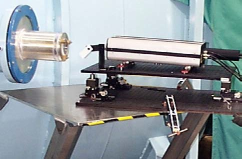
Figure 3. A dynamic interferometer measures a test sample in a vacuum chamber through a view port. (Courtesy Ball Aerospace). Image Credit: 4D Technology
Stability of Support Structures
Scheduled for space deployment in 2013, the James Webb Space Telescope (JWST) has faced several unique metrology challenges. One of these is the requirement to manage the dimensional stability of the support structure of the primary mirror over time, and at cryogenic temperatures.
A representative test structure was constructed to validate stability prior to flight. The test schedule required three weeks of almost constant measurements of the diffuse, large structure within a cryogenic chamber.
Electronic Speckle Pattern Interferometry (ESPI), an established technique for the quantification of diffuse surfaces, was selected for the test. A dynamic phase shifting speckle interferometer was positioned several meters from the test article, outside of the test chamber.
The equipment collects all phase data across the whole structure simultaneously for the duration of a single laser pulse (9 ns).
Figure 4a outlines the position of the test article within the cryogenic chamber. Figure 4b presents the test results from the dynamic interferometer. Using this method, out-of-plane deflections of tens of nanometers across hundreds of microns can be quantified.
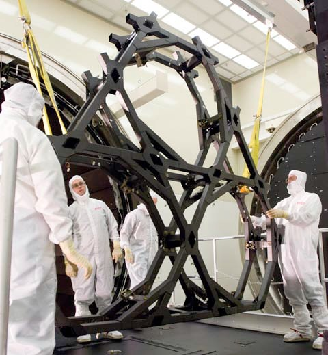
Figure 4a. The support structure for the James Webb Space Telescope undergoes cryogenic testing for dimensional stability. (Courtesy Northrop Grumman ATK Space Systems). Image Credit: 4D Technology
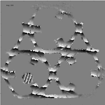
Figure 4b. Dynamic ESPI interferometry measurement data for the structure. (Courtesy NASA/Goddard). Image Credit: 4D Technology
Mirror Segment Alignment
A technique was also required by the JWST project to confirm that the primary mirror’s segments, which are folded for launch, will conform to within sub-wavelength tolerance during deployment. The measurement range of a traditional interferometer fails to capture the initial misalignment between segments due to their size.
A multiple wavelength dynamic interferometer was utilized for this application. The instrument is able to measure the initial misalignment as it generates a more extended ‘synthetic’ wavelength. The wavelength is stepped down for additional resolution as the segments are manipulated into alignment.
Verifying Adaptive Optics
Adaptive optics are now used on either the primary or secondary elements of many large telescopes to negate the influence of dynamically changing atmospheric factors. The adaptive system’s actuators are usually piezo elements fixed to the back of flexible components.
To comprehend the modal response of an optic to fluctuations in the actuators, sensors have been utilized to quantify movement at specific points on an optic, a low-resolution, time-intensive solution.
Due to its efficient acquisition time, dynamic interferometry can be employed to image an optic while it is being actuated to calibrate and verify the actuators’ response. The dynamic system demonstrates the 3D response of the complete optic, offering a full image of the performance of a control system.
Testing Aspheric Optics
Aspheric optics are now included more often in designs to enhance performance and simplify the composition of a system.
To validate the performance of a surface with a highly complex shape, a computer-generated hologram (CGH) is used to change the collimated or spherical test beam into the aspheric wave front necessary to measure the optic.
Along with the challenges of turbulence and vibration, CGHs face an additional challenge. Test setups lack efficiency, and return less than 1% of the laser power to the interferometer.
To provide enough power to enable measurement, dynamic, Helium-Neon laser interferometers have been produced with a 7 to 15 milliwatt output (compared to the 1 to 2 milliwatts for traditional instruments).
These systems usually offer a beam ratio control to balance the reference and test beams and enhance contrast and measurement quality.
Conclusion
A range of technological achievements, both in manufacturing and opto-mechanical design, has led to advances in astronomy.
Dynamic interferometry has been a notable contributor to the production of the modern generation of space and ground-based telescopes and will continue to be an enabling technology for projects in development currently.
Acknowledgments
Produced from materials originally authored by Mike Zecchino from 4D Technology.
Portions of this article appeared as Dynamic Metrology Perfects Reflections, Laser Focus World, February 2008.

This information has been sourced, reviewed and adapted from materials provided by 4D Technology.
For more information on this source, please visit 4D Technology.