The earliest attempt in the industry to link different viscosity cups' outcomes and associate each with mathematical formulas based on core measurements was made by a sub-committee within ASTM Committee D-1 on Paint, Varnish, Lacquer, and Similar Products. The findings of this effort were featured in the ASTM Bulletin of October 1950, No. 169.
In this mentioned study, there were formulas devised that could handle the non-linear behavior observed in the lower range of each cup due to turbulence from eddy currents at the opening. This allowed a comparison of outcomes among the 17 distinct cup types over specified timeframes.
The study encompassed results from a survey within the industry about the favored viscosity measurement tools. There was a strong inclination toward the Ford Viscosity Cup series for devices involving cups.
Basing decisions on this study and the inclination toward the Ford Viscosity Cup series, the ASTM implemented the ASTM Designation D 1200 in 1954 as a Standard Method of testing for the Viscosity of Paints, Varnishes, and Lacquers using the Ford Viscosity Cup. Some minor adjustments were made to this method in 1958, which received reapproval in 1965.
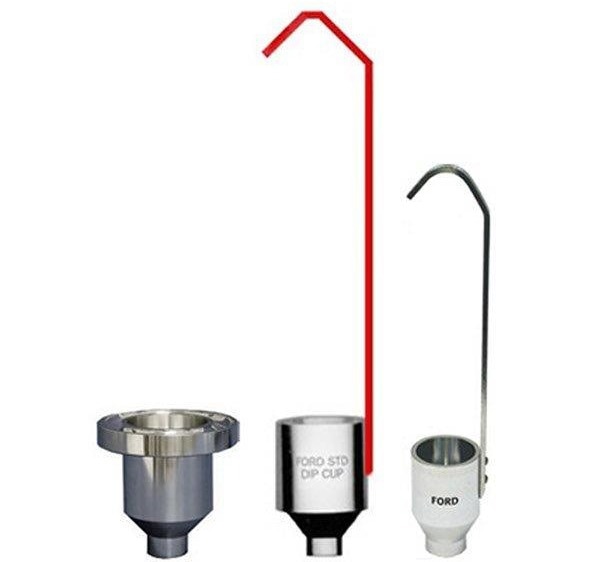
Image Credit: Paul N. Gardner Company, Inc.
The dimensions of the cup and orifice were detailed in D 1200-58 (1965). A graph was introduced instead of using the flow formulas from the earlier study. It linked viscosity in stokes to efflux time in seconds for Ford Viscosity Cups 2, 3, and 4.
The lines on the graph for Cups 3 and 4 closely matched the earlier work, except around the lower usable range. However, there is no comparative data for Cup Number 2 since it was not part of the original study.
ASTM revised the method in 1970, releasing it as D 1200-70 in subsequent standards. The series' dimensions were shifted to the metric system, but the actual measurements remained unchanged.
Perhaps the most significant change was the graph of "Standard Viscosity Curves for Ford Cups" being reduced to one-fourth of its original size. This alteration happened because, for the first time, the method's appendix included a flow formula for each of the three cups in the series.
The intention behind the flow formulas added in the D 1200-70 appendix seemed to align with the curves in D 1200-58’s graph. However, this attempt showed even more deviation from the 1950 published work.
The structure of the mathematical formula raises suspicion as it differs not only between the three cups in the series but also from the earlier published work.
Most Ford #3 and #4 viscosity cups currently in use are thought to closely match the definitions for these cups outlined in the October 1950 ASTM Bulletin, No. 169.
However, other cups, like the Ford #2 cup, are produced to comply with either ASTM Method D 1200-58 or ASTM Method D 1200-70.
Comparing results from these various cups should not pose significant issues as long as the outcomes fall within specified efflux time limits.
For results to theoretically align within a 5% range, the efflux limits for the #2 cup should be between 40 and 100 seconds, the #3 cup between 22 and 120 seconds, and the #4 cup between 25 and 100 seconds.
Background Information on Ford Viscosity Cups
The Paul N. Gardner Company is pleased to provide customers with background information on viscosity measurement and the development of the Ford Viscosity cup, a key tool for measuring this property.
A previous study cataloged over 90 viscosity-measuring devices. About one-third were rotational, another third were orifice capillary flow types, and the remaining third were evenly split among bubble-ball-plate resistance devices, time-retention devices, and miscellaneous mechanisms.
This substantial number underscores the significance of this property and hints at the challenge of accurately determining it. The provided information aims to guide users of viscosity-measuring equipment in understanding the various types and factors that influence measurements.
General
Every fluid exhibits a specific resistance to altering its shape, while many solids gradually give way to forces aiming to change their form. This characteristic, akin to internal friction, is termed viscosity.
In classical physics, the viscosity of a substance is defined as the sideways force per unit area between two horizontal planes, one stationary and the other moving at a standard velocity, within the substance-filled space, measured at a unit distance apart.
This measurement is articulated in dyne seconds per square centimeter or poises. One poise is equivalent to 100 centipoises.
Rotational Instruments
Hence, the prevalence of rotational instruments becomes apparent. Whether they follow a "bob in a cup" model, utilize a "cone and plate" setup, or any variation thereof, their readings, determined by understanding the surface area in contact with the substance and the gap between these surfaces, are expressed in fundamental units—poises.
Rotational tools find extensive use in research and development labs, designed to handle a broad spectrum of viscosity levels. More sophisticated variants offer measurements at different shear rates, catering to diverse studies on a substance's viscous traits. Additional features like automatic recorders can also be included.
However, drawbacks accompany these rotational instruments. Due to complexity, these instruments often exhibit considerable size and unwieldiness and may require delicate handling and specialized techniques to yield accurate results. Moreover, the costliness adds to the considerations when opting for use.
One significant challenge lies in temperature management. When subjected to high shear rates, the substance being measured heats up, necessitating intricate temperature sensing and control systems to maintain a constant temperature. The substantial impact of temperature will be discussed further.
Orifice - Capillary Instruments
Capillary tube instruments work well for measuring less viscous substances. These instruments come in various setups, but at their core, they include a reservoir linked by a capillary tube of specific length and internal diameter to another reservoir placed lower.
To measure, the substance gets filled precisely into the upper reservoir, and the time it takes for this quantity to flow to the lower one gets noted. Now, density steps into the equation. A denser material should move faster through the capillary tube than a less dense one at the same viscosity level.
Back to classical physics teachings: the substance's flow volume through a tube relates directly to the flow time, the pressure difference across the tube, the fourth power of the tube's radius, and inversely to the tube's length and the substance's viscosity.
Kinematic viscosity, or the stoke, defines the ratio of poise viscosity to density, where 100 centistokes equal one stoke (stokes = poises ÷ density).
From this definition, it is clear how capillary tube instruments connect directly to fundamental measurement units. However, if gravity causes the pressure drop across the tube, density plays a role, and the outcomes are measured in stokes.
The capillary tube instrument has been a reliable tool for measuring low-viscosity substances, but it does come with limitations. It is delicate, can only handle very low shear rates, and is not convenient for fieldwork.
Viscosity cups, however, are akin to a development from capillary tube instruments. These cups feature shorter and wider tubes and typically hold a larger sample compared to the capillary tube's reservoir.
Despite these dimensional changes, the relationships mentioned earlier still apply. However, there is a deviation from linearity at the lower end of each cup's range, particularly noticeable in cups with shorter tube lengths due to eddy currents forming at higher flow rates.
Given that gravity drives material flow from a viscosity cup and density matters, measurements are in terms of kinematic viscosity or stokes.
Viscosity cups see widespread use for several reasons: they are surprisingly accurate, sturdy enough for field use, relatively easy to clean, and come at a modest cost.
The development of viscosity control cups has progressed in two main directions: precision instruments for quality control labs and simpler versions for field use. However, the challenge with the latter is often the lack of standardization and direct ties to fundamental measurement units.
Other Types
The exploration of the remaining third of surveyed instruments' various types goes beyond the scope of this text. For more details, it is recommended to refer to publications like the ASTM Manual 17 - Paint & Coating Test Manual Gardner-Sward Handbook, 14th edition.
Liquid - Solid Mixtures
When solid particles like pigments are thoroughly mixed with liquids, their "interfacial friction" adds to the "internal friction" of the liquid, affecting any viscosity measurement.
Emulsions might show similar behavior. Naturally, when the ratio of solid particles to liquid is higher, the impact of "interfacial friction" becomes more noticeable.
These mixtures of liquids and solids introduce complexity to viscosity measurement. Some materials will not flow unless a force surpassing a certain minimum is applied. Others may demonstrate a decrease in viscosity as the shear rate rises, while some may show an increase in viscosity with higher shear rates.
Assessing the flow characteristics of mixtures with high solid content is best done using rotational equipment where the shear rate can be adjusted. However, a detailed discussion of such mixtures is not within the scope of the provided text.
Temperature
Temperature plays a crucial role in viscosity measurement, often overlooked in simpler devices.
It significantly impacts various physical measurements. For instance, a slight change in temperature causes different effects across materials. Consider a soft iron bar: its length changes by 0.00121% per degree Celsius, typically negligible.
But for water, under similar conditions, the change is over 20 times greater, highly impacting precise measurements like Weight per Gallon cup calibration.
In viscosity measurement, temperature's impact is more pronounced. Refined mineral oils, used for calibrating viscosity instruments, can change viscosity by over 5% per degree Celsius around 25 °C , which is substantially higher than water's impact on volume or a soft iron bar's length.
The impact on water volume from temperature is more than 200 times, while for the length of a soft iron bar, it is over 4000 times.
Typically, viscosity change due to temperature is tied to the viscosity itself: higher viscosity means more temperature impact.
Take, for instance, calibrating oils ranging from 50 to 500 centistokes; these materials are less sensitive to temperature compared to most others used for viscosity measurement.
Common errors in temperature measurement, consequently affecting viscosity measurement, often include one or more of these issues: the thermometer covering too broad a range, resulting in insufficient sensitivity, and the thermometer experiencing a significant time lag unsuitable for the intended application.
The thermometer's "thermal well" effect might exceed the application's needs. Incomplete mixing of the sample leads to non-uniform temperature distribution. Temperature changes during measurement occur due to equipment surfaces being at a different temperature than the sample.
The majority of materials alter their viscosity with temperature. For materials measured using viscosity cups, this change typically falls within 3% to 8% per degree Celsius. Generally, higher viscosity implies a more significant alteration.
To ensure accuracy, it is crucial to measure temperature simultaneously with viscosity cup readings.
When numerous determinations on similar products within the same viscosity range are required, creating a graph to convert measured temperature and viscosity cup efflux seconds to seconds at a specified temperature, often 25 °Celsius, can be beneficial.
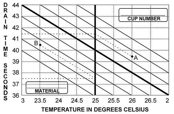
Image Credit: Paul N. Gardner Company, Inc.
Three variables need consideration: viscosity, efflux time, and temperature. Graphically represented as seen in the previous example, all three can be depicted through a family of curves. Viscosity levels are showcased by diagonal lines, ascending from the lower left to the upper right.
To prepare such a graph for a specific material, use readings from any of the Ford series cups within a confined temperature range, mirroring the example. Typically, within this range, the data plots form a straight line, like the wide diagonal line depicted.
Create parallel lines to represent various viscosity levels on the graph. Record the material and the Ford cup designation with the cup number.
Utilize this graph by plotting measured temperature and efflux seconds. For instance, at point "A" in the example, values are 26 °C and 39.5 seconds. Follow the diagonal lines to intersect the double vertical line at the target temperature, 25 °C.
By reading horizontally to the left, the corrected efflux seconds at 25 °C are found to be 41.5 seconds. Similarly, at point "B" in the example, a reading taken at 23.5 °C, when corrected to 25 °C, changes from 40.5 to 37.5 seconds.
When adjusting for a measured temperature close to but not exactly as specified, caution is essential. Even within the limited range of ±2.0 °C, the relationship between viscosity and temperature might not be entirely linear. Any thinning materials used to modify viscosity could alter the rate of this relationship.
Gardco's viscosity cups are calibrated using standard "G" Series oils, whose centistoke viscosity is traceable to the National Institute of Standards and Technology. These oils can be obtained from the Paul N. Gardner Company.
The graph above displays the viscosity cup designation and the standard oil utilized for its calibration. Typically, cup calibration occurs at 25 °C, depicted on the graph by bold lines intersecting with the curve within the circle. A set of these graphs, one for each cup in the series, accompanies every Ford Cup sold by Gardco.
The viscosity of most liquids, including standard oils, varies with temperature. The efflux time in seconds for the specified cup-oil combination is displayed in the graph above, ranging from 20 to 27 °C . Within these limits, the graph allows for reasonably accurate checks of the cup using the indicated oil.
For optimal accuracy, it is recommended to utilize the standard oil's labeled viscosity at 25 °C. Converting viscosity from centistokes to efflux time in seconds relies on the formula or table defining the cup's characteristics. Below, find a conversion between degrees Celsius and Fahrenheit.
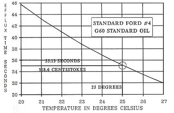
Image Credit: Paul N. Gardner Company, Inc.
Each viscosity cup sold, as an added customer service by the Paul N. Gardner Company or licensed distributors, comes with the relevant cup formula and table for reference.
Source: Paul N. Gardner Company, Inc.
| Temperature Scale Conversion Between Celsius & Fahrenheit |
| Degrees |
|
Degrees |
| Celsius |
Fahrenheit |
Celsius |
Fahrenheit |
| 20.0 |
68.0 |
|
23.6 |
74.5 |
| 20.1 |
68.2 |
23.7 |
74.7 |
| 20.2 |
68.4 |
23.8 |
74.8 |
| 20.3 |
68.5 |
23.9 |
75.0 |
| 20.4 |
68.7 |
24.0 |
75.2 |
| 20.5 |
68.9 |
24.1 |
75.4 |
| 20.6 |
69.1 |
24.2 |
75.6 |
| 20.7 |
69.3 |
24.3 |
75.7 |
| 20.8 |
69.4 |
24.4 |
75.9 |
| 20.9 |
69.6 |
24.5 |
76.1 |
| 21.0 |
69.8 |
24.6 |
76.3 |
| 21.1 |
70.0 |
24.7 |
76.5 |
| 21.2 |
70.2 |
24.8 |
76.6 |
| 21.3 |
70.3 |
24.9 |
76.8 |
| 21.4 |
70.5 |
25.0 |
77.0 |
| 21.5 |
70.7 |
25.1 |
77.2 |
| 21.6 |
70.9 |
25.2 |
77.4 |
| 21.7 |
71.1 |
25.3 |
77.5 |
| 21.8 |
71.2 |
25.4 |
77.7 |
| 21.9 |
71.4 |
25.5 |
77.9 |
| 22.0 |
71.6 |
25.6 |
78.1 |
| 22.1 |
71.8 |
25.7 |
78.3 |
| 22.2 |
72.0 |
25.8 |
78.4 |
| 22.3 |
72.1 |
25.9 |
78.6 |
| 22.4 |
72.3 |
26.0 |
78.8 |
| 22.5 |
72.5 |
26.1 |
79.0 |
| 22.6 |
72.7 |
26.2 |
79.2 |
| 22.7 |
72.9 |
26.3 |
79.3 |
| 22.8 |
73.0 |
26.4 |
79.5 |
| 22.9 |
73.2 |
26.5 |
79.7 |
| 23.0 |
73.4 |
26.6 |
79.9 |
| 23.1 |
73.6 |
26.7 |
80.1 |
| 23.2 |
73.8 |
26.8 |
80.2 |
| 23.3 |
73.9 |
26.9 |
80.4 |
| 23.4 |
74.1 |
27.0 |
80.6 |
| 23.5 |
74.3 |
|
| F°=(C° x 1.8)+32 C°=(F°- 32)÷1.8 |
Care of Cup
The GARDCO viscosity cups are precise instruments. To maintain their original condition and calibration, it is advisable to clean them after each use using an appropriate solvent and a soft brush or a lint-free cloth. Careful attention should be paid to cleaning the orifice to prevent leaving any deposits or scratches on the internal surfaces.
Top of Form
It is a good practice to keep one or more standard oils handy, which can be used periodically to ensure that each cup retains its initial calibration. These oils are available from Gardco.
The "seconds" values in the table below are approximate and should be recalculated using the earlier provided formula and the precise centistoke value mentioned on the standard oil label.
Source: Paul N. Gardner Company, Inc.
| Approximate Efflux Seconds From Standard Ford Cups |
| Cup No. |
Standard Oil |
Efflux Seconds |
| 0 |
G6 |
93 |
| 1 |
G10 |
84 |
| 2 |
G35 |
64 |
| 3 |
G60 |
56 |
| 4 |
G60 |
35 |
| 5 |
G200 |
39 |
| Divide Values By 2 For Dip Cups |
To determine the precise efflux seconds, you can either substitute the centistoke value from the oil bottle label into the provided conversion formula sheet accompanying the cup and solve the formula, or locate the label centistoke value within the body of the conversion table and read the corresponding efflux seconds.
CAUTION: Silicone fluids are not suitable for calibrating viscosity cups. These fluids alter the interaction between the cup surface and the test material, leading to changes in cup calibration.
According to ASTM D 445: "Viscometers used for silicone fluids should be exclusively reserved for such fluids. Solvent washings from these viscometers should not be used for cleaning other viscometers."Top of Form
Certification
For an additional cost, any specific Gardco Standard or Dip Cup - orifice combination can be certified within a precision of 0.1 seconds and 0.01 °C . This certification involves using a standard oil chosen for the midrange of that combination.
The viscosity of the oil and the temperature measuring devices used for certification are traceable to the National Institute of Standards and Technology. This certification aligns with the requirements of ANSI/NCSL Z540-1 as applicable. However, it is important to note that this certification becomes invalid if the cup orifice is interchanged or replaced.
The details provided here, or conveyed by us through any other means, stem from our independent research and are deemed accurate. Nevertheless, NO WARRANTY, EXPRESS OR IMPLIED, IS PROVIDED REGARDING THE ACCURACY OF THIS INFORMATION, THE OUTCOMES DERIVED FROM ITS USE, OR ASSURANCE AGAINST PATENT INFRINGEMENT. This information is shared with the understanding that the recipient will conduct their tests to ascertain its suitability for their specific purpose.
Auxiliaries
A stopwatch with a seven-jewel movement, measuring 1/5 second, serves as a suitable timer. To aid its use, a practical stopwatch stand is also available. Alternatively, a digital electronic timer, capable of a 10-hour range and measuring to 1/100 second intervals, is another appropriate timing device.
An additional helpful tool is a square glass plate that, when positioned atop a filled cup, prevents material from flowing through the orifice. It can also assist in removing excess material from an overfilled cup. This glass plate is affixed with a circular level, aiding in leveling the cup support.
The preferred thermometer should offer readability to the closest 0.1 °C. The glass thermometer endorsed by Gardco meets this criterion, being scaled accordingly. It measures 4.5 inches in length and spans a range from 20 to 30 °C. For additional expanded-scale glass thermometers, refer to the following pages.
A 250 ml stainless steel beaker serves as a convenient receptacle for the efflux stream from the Gardco Standard Ford Cup. Being metallic, it rapidly conducts heat, facilitating any necessary temperature adjustments of the sample. Additionally, its size is sufficient to accommodate the cup's body for drainage or cleaning purposes.
Tripod Support
To offer optimal support for the new Gardco Standard Ford Viscosity Cups and other cups of similar types, specially designed tripod support has been developed.
Illustrated above on the right, this support structure is crafted from aluminum. Its adjustable leg lengths enable precise leveling of the viscosity cup, ensuring the best possible results. The spread of the tripod legs is ample, providing excellent stability and minimizing the likelihood of accidental spills of the cup contents.
Glass Thermometers for Viscosity Measurement by Efflux Cups
The accuracy and significance of viscosity measurements are closely tied to the accuracy of temperature measurements.
Temperature is one of the critical parameters influencing viscosity, akin to both the height and width required to define a rectangle. Virtually all liquids alter their viscosity with temperature fluctuations.
The rate of viscosity change is more pronounced at higher viscosity levels, and this change does not follow a linear pattern. Even standard oils used for viscosity cup calibration demonstrate viscosity alterations within the range of 3% to 8% per degree Celsius at the standard operating temperature of 25 °C.
Glass thermometers are preferable as reference temperature devices for viscosity measurements due to their likelihood of becoming unusable if damaged or falling out of calibration. This leaflet details suitable standardized glass thermometers listed in ASTM methods for this purpose.
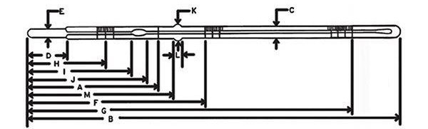
Image Credit: Paul N. Gardner Company, Inc.
The accuracy of viscosity readings heavily relies on using a glass thermometer with a continuous mercury column, readable to the nearest tenth of a degree Celsius or an equivalent standard. When using metallic dial thermometers, the risk of inaccurate readings due to potential damage or mishandling, such as dropping, exists.
Similarly, thermocouple devices may fall out of calibration, compromising accuracy. Even if a glass thermometer is employed but can only be read to the nearest degree, it might lead to misleading results.
Therefore, it is advisable to have a glass thermometer readable to at least the nearest tenth of a degree Celsius as a standby reference. Regularly checking all other temperature-measuring devices against this standby thermometer ensures the maintenance of accurate temperature-measurement capabilities.
Glass thermometers meeting the specifications of either ASTM 17C or 17F have proven adequate for direct use or as a reference instrument in conjunction with efflux cup viscosity measurement.
For laboratory applications, the further expanded scale ASTM specified 45 °C or 45 °F might be preferable. Detailed specifications for each of these thermometers are provided in the following tables:
Source: Paul N. Gardner Company, Inc.
| Technical Data |
| ASTM Number |
17C |
17F |
45C |
45F |
| ASTM Name: |
Saybolt Viscometer |
Saybolt Viscometer |
Kinematic Viscosity |
Kinematic Viscosity |
| Range: |
19 to 27C |
66 to 80F |
23.6 to 26.4C |
74.5 to 79.5F |
| For Test At: |
25C |
77F |
25C |
77F |
| Immersion |
Total |
Total |
Total |
Total |
| Graduations |
| Subdivisions |
0.1C |
0.2F |
0.05C |
0.1F |
| Long Lines at Each: |
0.5C |
1F |
|
0.5F |
| Number at Each: |
1C |
2F |
|
1F |
| Max. Scale Error: |
0.1C |
0.2F |
|
0.2F |
| Inscription: |
ASTM 17C |
ASTM 17F |
ASTM 45C |
ASTM 45F |
| Heating Limit: |
100C |
212F |
104C |
220F |
| Total Length (B): |
275/10.8* |
275/10.8* |
305/12.0* |
305/12.0* |
| Stem O.D. (C): |
6.5/0.26* |
6.5/0.26* |
7.2/0.28* |
7.2/0.28* |
| Bulb length (D): |
30/1.18* |
30/1.18* |
50/1.97* |
50/1.97* |
| Bulb O.D. (E): |
5/0.20* |
5/0.20* |
6.5/0.26* |
6.5/0.26* |
| Min. Scale Ht. (F): |
143/5.63* |
143/5.63* |
142/5.59* |
142/5.59* |
| Max. Scale Ht. (G): |
227/8.94* |
227/8.94* |
205/8.07* |
205/8.07* |
| Ice Point Range: |
NA |
NA |
|
31.5 to 32.5F |
| I.P. Scale Ht. (H): |
NA |
NA |
82/3.23* |
82/3.23* |
| Min. Chamber Ht. (I): |
NA |
NA |
100/3.94* |
100/3.94* |
| Max. Chamber Ht. (J): |
60/2.36* |
60/2.36* |
125/4.92* |
125/4.92* |
| Ring O.D. (K): |
9/0.35* |
9/0.35* |
NA |
NA |
| Ring Length (L): |
5.5/0.22* |
5.5/0.22* |
NA |
NA |
| Ring Ht. (M): |
114/4.49* |
114/4.49* |
NA |
NA |
* Millimeters/Inches — Values are average.
NA Not Applicable. |

This information has been sourced, reviewed and adapted from materials provided by Paul N. Gardner Company, Inc.
For more information on this source, please visit Paul N. Gardner Company, Inc.