Sponsored by MKS NewportReviewed by Olivia FrostAug 26 2026
A motion device, such as a stage, generates the desired motion along an optimum trajectory. Such devices must be able to reliably and consistently achieve a specified target position.
Friction between moving parts, guide quality, or bending caused by moving loads can all deviate the motion from this ideal trajectory or cause variations between the actual and desired positions.
This article covers the parameters that influence the motion of these devices, as well as methods for characterizing their positional precision and accuracy.
Positioning Basics
Any positioning stage is considered to have six degrees of freedom: three linear translations along the x, y, and z axes, and three rotations around those same axes. The goal of a stage is to generate motion along an optimum trajectory, which necessitates limiting motion to specific degrees of freedom.
Any motion in non-constrained directions will cause a divergence from the ideal trajectory and/or position.
For example, a linear translation stage constrains motion along an ideal straight line. A linear stage's runout is the linear (rather than angular) fraction of off-axis error and represents the deviation from the desired, ideal straight-line motion. Runout consists of two orthogonal components known as flatness and straightness.
Figure 1 shows a linear stage where the ideal straight-line motion is limited to the x-axis. In this situation, flatness deviation is displacement along the z-axis, whereas straightness deviation is displacement along the y-axis.
Similarly, angular runout (or tilt) of a linear stage refers to the rotation of the moving functional point or the point at which a measurement and/or process is performed. Angular runout consists of three orthogonal components known as pitch, roll, and yaw (see Figure 1), and their potentially complex interaction.
If multiple stages are coupled to form a multi-axial system, cross-coupling can occur, which implies that a change in one axis can cause an unintended change in another.
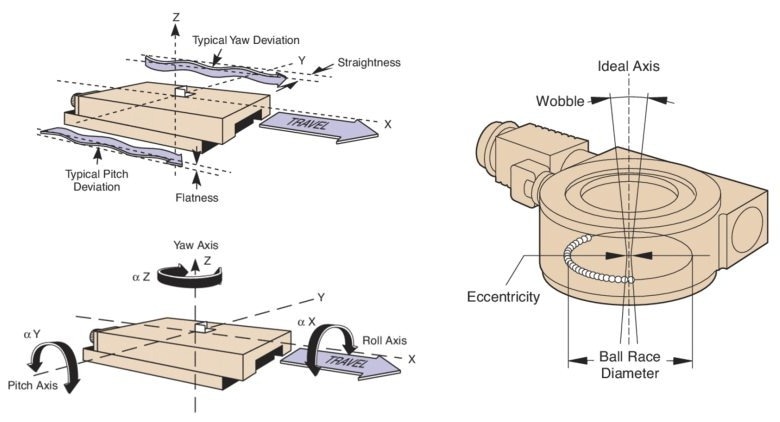
Figure 1. Flatness and straightness runout of a linear stage (upper left). Roll, pitch, and yaw angular runout of a linear stage (lower left). Off-axis deviations in a rotary stage (right). Image Credit: MKS Newport
Eccentricity of a rotational stage is the radial (perpendicular to the axis of rotation) departure of the center of rotation from its mean position when the stage revolves one revolution (Figure 1). This is also known as radial runout.
A perfectly centered stage with properly aligned bearings would have no eccentricity. The wobble of a rotary stage is the tilt of the axis of rotation relative to the ideal axis throughout one revolution.
It is most easily identified as a cyclic tilting of a stage's revolving surface or table top, and is typically caused by imperfect bearings, similar to eccentricity. A stage must not only follow an optimal trajectory, but also reach and retain a specific target position on a consistent basis.
The reversal error is the distance between the actual positions attained and the desired position when approached from opposite directions (Figure 2). This number combines backlash and hysteresis.
Backlash is caused by relative movement between interacting mechanical components of a drive system that does not generate output motion. Mechanical deformation and clearance between mechanical parts, such as gear teeth, are also contributing causes.
Not all systems experience backlash, but when they do, it primarily impairs bidirectional repeatability (see below). Motion controllers can correct for backlash since it is reproducible. Hysteresis is a component of reversal error that is determined by the system's recent past.
It is caused by elastic forces in multiple components and occurs when the forces acting on a system reverse direction. Hysteresis influences both bidirectional repeatability and accuracy. Unlike backlash, hysteresis is present in all mechanical systems, even if its magnitude is low.
While reversal error refers to a stage's capacity to attain the desired position, position stability refers to the ability to hold a position within a particular position range during a given time interval. It is the sum of drift and vibrations.
Drift is the slow movement away from a steady place; it is mostly dependent on lubricant migration and temperature fluctuations. Vibrations are rapid, small-amplitude alternating motions caused by the surroundings, such as noise from airflow, fans, and electronic devices, like motor drivers.
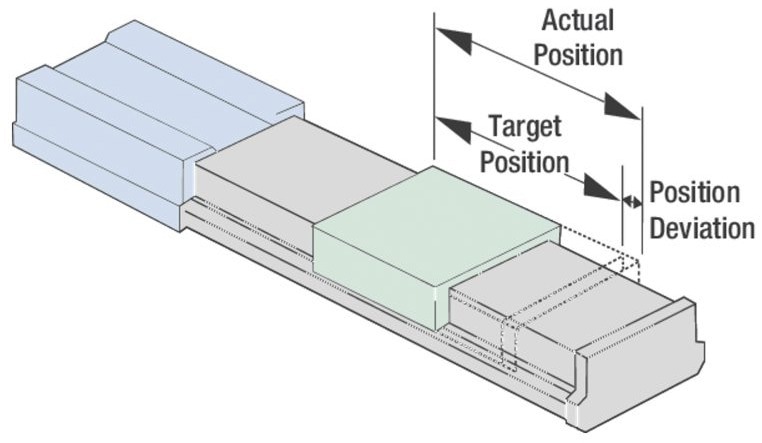
Figure 2. Illustration of a position deviation for a linear stage, which is the actual or measured position reached by the functional point minus the target position. Image Credit: MKS Newport
In addition to position, the rate of change of position, or speed, is a critical factor in motion systems. The maximum speed specification is based on the stage's usual load capacity (see below). Higher speeds are feasible with lesser loads or larger motor drivers. Minimum speeds are heavily reliant on a motion system's speed stability.
Speed stability is a measure of a motion system's ability to maintain a steady speed within defined limitations, typically expressed as a percentage of the intended speed. Acceleration is the rate at which speed changes, and it is generally controlled to achieve maximum speed within a specified time.
Friction, defined as the resistance to movement between two surfaces in contact, can have a considerable impact on a stage's speed, stability, and acceleration. Friction-causing elements can include drag, sliding friction, depleted lubrication, system wear, and lubricant viscosity.
Stiction is the static friction that must be overcome before a body at rest may move. Because static friction is often greater than moving friction, the force necessary to impart motion exceeds the force required to keep the body moving.
As a result, when a force is first applied, the body will "jump" and overshoot in position and/or speed.
Load capacity is the maximum permitted force that can be delivered to a stage in a given direction while still matching stage standards. This maximum force comprises both static (mass times gravity) and dynamic forces (mass times acceleration). Dynamic forces must incorporate all external forces acting on the stage, such as vibrations.
The amount of acceleration a stage can impart to a mass is limited by the accelerating force it can generate without exceeding the load capacity. The centered normal load capacity is the maximum load (centered on the carriage and perpendicular to the axis of motion) that may be applied to a linear stage (Figure 3). For rotary stages, the centered normal load is the maximum load along the axis of rotation.
Transverse load capacity, also known as side load capacity, is the maximum load that may be applied perpendicular to the axis of motion and across the carriage surface. This is usually smaller than the standard load capacity.
Axial load capacity refers to the maximum load along the drive train's direction. For vertically mounted linear stages, the axial load capacity typically limits the required vertical load capacity. When the load is not centered, a stage's maximum load capacity decreases.
Inertia is a measure of a load's resistance to changing speed. The bigger the inertia, the more force is necessary to accelerate or decelerate the load. If the amount of force available is limited, the permitted acceleration and deceleration must be regulated to a reasonable level.
Inertia is calculated as the product of the mass of each element and its squared distance from the axis of rotation. The maximum inertia set for the rotary stage is based on the available torque.
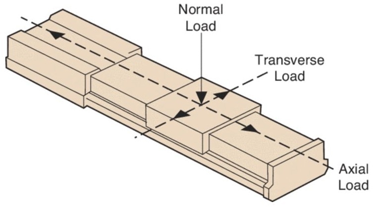
Figure 3. A stage's different load capacities. Image Credit: MKS Newport
Motion Control Specifications
When selecting the appropriate positioner for a certain application, it is common to consider product parameters such as repeatability and accuracy. Repeatability is frequently conflated with accuracy; as shown in Figure 4, however, a system can be highly repeatable while lacking accuracy.
Accuracy is a measure of how closely a particular displacement adheres to an agreed-upon norm.
For example, runout is also referred to as straight-line accuracy. The test setup, climatic circumstances, and the displacement measurement process can all have a significant impact on a motion system's accuracy.
The bulk of current controllers allow for linear error compensation simply by inserting a compensation factor into the controller. As a result, accuracy after compensation is often provided for each stage.
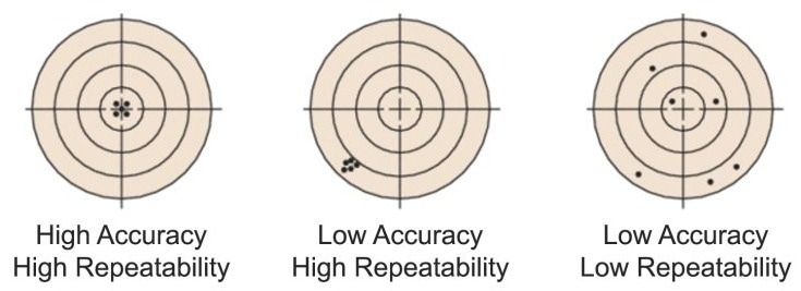
Figure 4. A depiction of the differences between accuracy and repeatability. Image Credit: MKS Newport
Repeatability is a measure of a positioning system's ability to place successively. It can be unidirectional (approaching the target position only from the same direction) or bidirectional (approaching the target position from either direction).
In many applications, the repeatability of a motion system is more significant than its precision; systematic errors can be accounted for and adjusted, but repeatability is the final limit that must be met after all corrections.
The fundamental concept of repeatability refers to a system's capacity to attain a commanded location across multiple attempts when approached from the same or different directions (Figure 5). Reversal error and position stability mostly define a system's repeatability.
Repeatability is vital for assuring quality in a variety of contexts: without sufficient repeatability in a manufacturing setting, there can be no reliable procedure to ensure that items are consistently made and satisfy the same requirements.
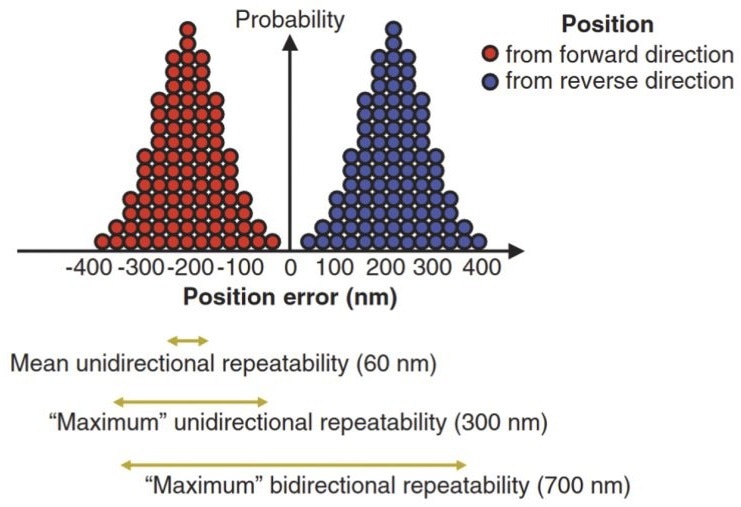
Figure 5. Measurements that yield a distribution of position errors define a motion control system's repeatability. Image Credit: MKS Newport
Resolution is the smallest increment that a motion system may be instructed to move and/or detect. A system may or may not be able to reliably perform incremental motions equal to the resolution.
Minimum incremental motion (MIM), also known as ‘practical resolution’, is the smallest increment of motion that a device is capable of consistently and reliably producing. Friction, load, external forces, system dynamics, controller, vibrations, and inertia can all affect motion output.
The MIM should not be confused with resolution, which is normally calculated using the smallest controller display value or encoder increment. Resolution can be much less than the smallest actual motion output, which is an important distinction that is often overlooked.

This information has been sourced, reviewed, and adapted from materials provided by MKS Newport.
For more information on this source, please visit MKS Newport.