Sponsored by MKS NewportReviewed by Olivia FrostSep 1 2026
Open-loop control is a technique that does not measure or act on a system's output. A closed-loop control technique, conversely, compares the system's output to the required input and takes remedial action to get the desired outcome.
Most piezoelectric systems and low-cost micrometer replacement actuators operate in an open loop. Electronic feedback technologies in closed-loop systems improve the capacity to precisely position and shift loads.
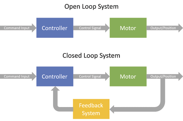
Figure 1. Open-loop vs. closed-loop motion control. Image Credit: MKS Newport
Open-Loop Motion System
The term "open loop" does not inherently suggest a crude system. Even low-cost open-loop devices can provide very precise incremental motions. Open-loop piezo-type devices, such as the picomotor, can achieve nanometer-scale incremental motions. Open-loop systems estimate the position of a motion device without an encoder.
In the case of a piezo device, the applied voltage indicates location. However, the relationship is imperfect due to the hysteresis and nonlinearities seen in popular piezo materials.
As a result, the standard picomotor actuator step size may not always match between two picomotors. As a result of the slip/stick mechanism, the step size varies with weight (Figure 2). Still, for the same picomotor with constant load, the step size remains constant.
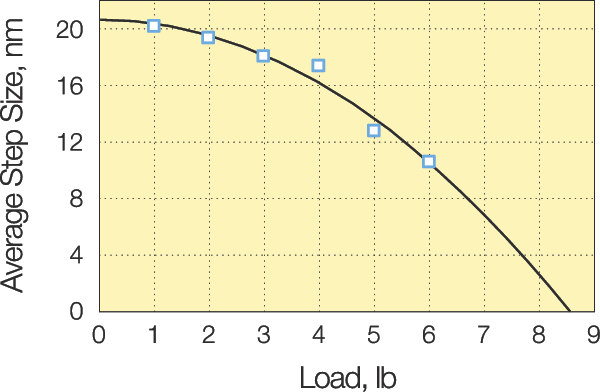
Figure 2. Picomotor average step size vs load. Image Credit: MKS Newport
Another factor influencing picomotor step size is direction, which is determined by the differential between expansion and contraction of the piezo stack (Figure 3). The difference between forward and backward step sizes varies greatly, ranging from 0% to more than 100%, but is always less than 30 nm.
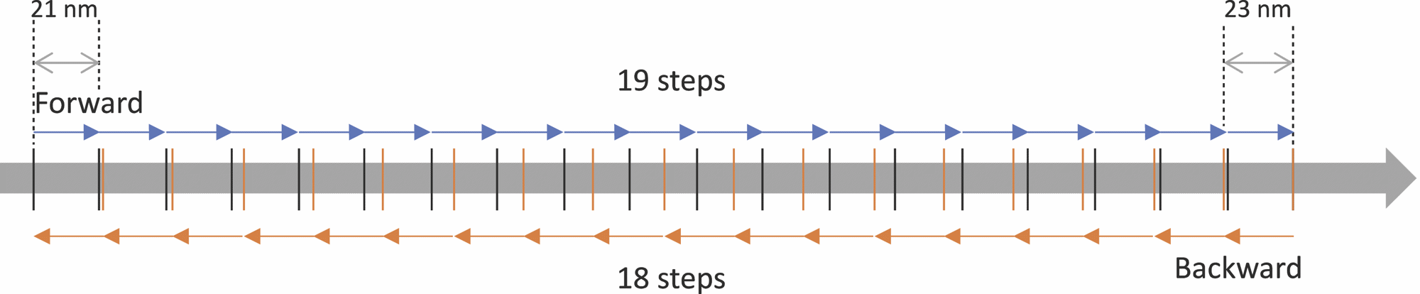
Figure 3. The variation between forward and backward step sizes in a picomotor (please note dimensions are not to scale). Image Credit: MKS Newport
Despite the variability in step size, it is still possible to adjust position in extremely small increments, allowing for delicate adjustments with excellent stability.
As shown in Figure 3, even if the picomotor moves ahead and then backward 18 steps, it will remain within 30 nm of its original position. With longer trips, this difference becomes more drastic. As a result, open-loop picomotors should be used for small adjustments.
It is usually preferable to close the loop on the main process that is being managed. For example, with mirror mounts in an optical beam path, it is advised to close the loop through the beam position using beam splitters and beam-position-sensing detectors, such as the Newport TM CONEX-PSD9 or CONEX-PSD10GE. These pieces of equipment enable determination of how to command the picomotors on the mirror to adjust the beam position.
In such a closed-loop application, a picomotor would not have been useful for actual adjustment.
A good example of this is beam alignment within a laser's cavity. After the cavity is closed, it is impossible to manually adjust the mirrors, but the adjustments should be no more than a few steps in either direction, making the open-loop picomotor an ideal fit.
Closed-Loop Motion System
It may be helpful to close the position loop on a picomotor. The major reason for doing this is when it is necessary to fully automate positioning, which means the system is not in its optimal position. The following figure is designed to aid understanding, but first consider the encoder resolution and step size.
The encoder resolution on the closed-loop picomotor is slightly bigger than the step size. This is because the aim is to command the picomotor to reach a specified encoder count, as shown in Figure 4.
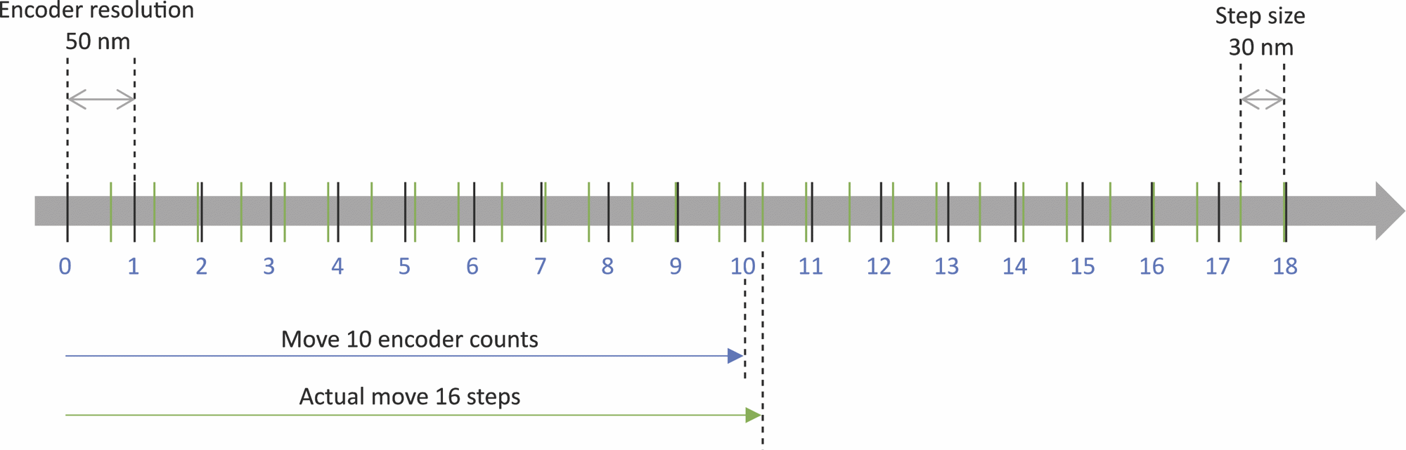
Figure 4. Encoder resolution vs. picomotor step size. Image Credit: MKS Newport
In Figure 4, the picomotor is commanded to move 10 encoder counts. To achieve this, the controller directs the picomotor to take 16 steps.
During the 16th step, the encoder reaches the 10th count, but because the picomotor has a fixed step size, it completes the step and oversteps the 10th count position. The worst-case scenario of this overstep always yields an inaccuracy smaller than the step size.
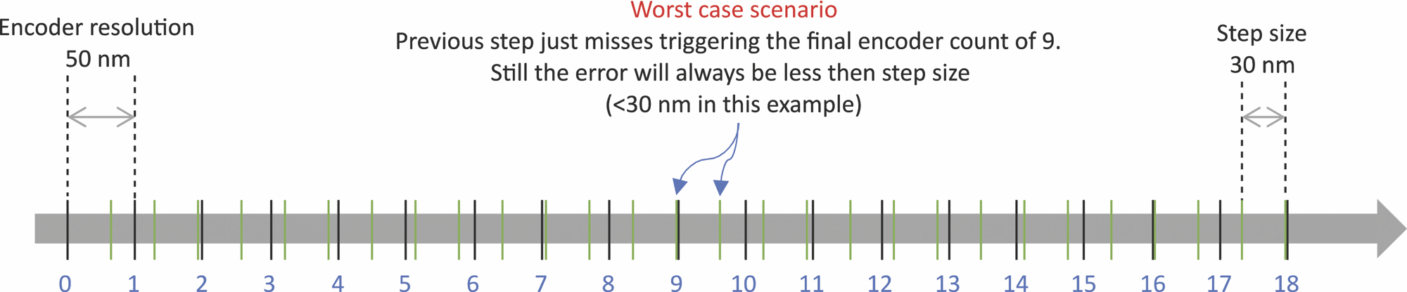
Figure 5. Worst-case scenario when previous motion step just misses triggering an encoder count. Image Credit: MKS Newport
If the encoder resolution is less than the step size, it causes issues when employing the actuator in an application. Figure 6 shows that the step size determines the position, and it is impossible to attain a certain encoder count between steps.
The encoder's impossible position makes it difficult for the controller and user to navigate to a location based on the encoder count.

Figure 6. Impossible encoder positions are located between minimum picomotor steps. Image Credit: MKS Newport
Now, consider the example discussed at the beginning of this section; imagine an application in which a linear stage carries a mirror mount.
The linear stage must move between two places, so the laser beam can strike one of two targets. Figure 7 shows the linear stage and picomotor in two different positions based on which target the laser beam strikes.
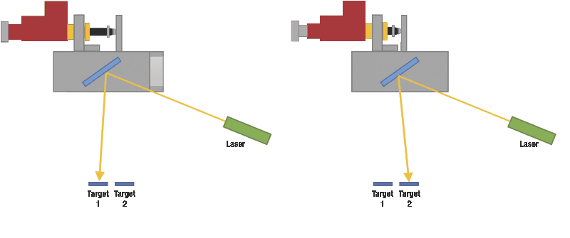
Figure 7. Linear stage and Picomotor in two different positions depending on which target the laser beam hits. Image Credit: MKS Newport
Assume the move is 10 mm in this case. This would imply 200,000 encoder counts (based on the 8311's encoder resolution of 50 nm), but as previously stated, the steps in one or the other direction might be significantly different; the average step forward is roughly 21.4 nm, and backward is 25.5 nm. That means 467,390 steps forward and roughly 392,157 steps back.
There is a significant difference in the number of steps, so an open-loop approach would be impractical unless the user had beam-position-sensing detectors, as aforementioned.
However, even if this were the case, it would be a much slower process, as it would require going back and forth between moving the picomotor one step, checking the position on the sensor, and then doing it repeatedly until the desired position is reached.
With a closed-loop picomotor, users simply tell the controller the number of encoder counts to move the actuator, and the controller optimizes acceleration, speed, and deceleration to reduce the time to reach the target position.
Conclusion
As seen above, the application will determine the appropriate picomotor (open or closed loop) to employ. Where relatively minor, infrequent adjustments are required in conjunction with greater system-level input, such as beam-path-position monitoring, open loop makes more sense, and the increased cost of closed loop is unnecessary.
Closed loops make greater sense when there are two or more well-known settings for the system to adjust to. In these types of applications, closed loops can be extremely useful in reducing the time it takes to get from one position to another.

This information has been sourced, reviewed, and adapted from materials provided by MKS Newport.
For more information on this source, please visit MKS Newport.