This article discusses temperature increase and ventilation in machine chambers.
1.Temperature Increase within the Chamber
Whenever positive displacement blowers (turbo-machines, compressors) are operated, the packaged units release a part of the power consumed by the drive motors into the ambient air as heat radiation. Electrical switchgear and pressurized pipelines with residual heat losses, for example frequency converters, also heat up the chamber (these effects are not addressed in the following descriptions).
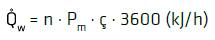
2.Radiated Heat Volume .jpg) w
w
Based on the packaged unit, some heat quantity (see Table 1) that results from the performance of the installed motor is released into the installation room.
Table 1. Heat volume as % of the motor power for all available Aerzen types
| Type |
Heat volume as % of the motor power |
Radiation factor ç of the motor power |
| Blower |
15 |
0.15 |
| Hybrid L/S |
10 |
0.10 |
| Hybrid H |
20 |
0.20 |
| Turbo with motor heat released into the room |
8 |
0.08 |
| Turbo with motor-heat dissipation via piping |
4 |
0.04 |
| Compressor |
25 |
0.25 |
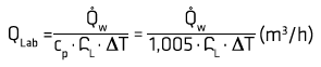
3.Required Cooling Air Flow QLab for Heat Dissipation
4. Room Ventilation
4.1 Suction of Positive Displacement Blower Outside the Installation Room via Suction Pipe
.jpg)
The above values are guide values for continuous operation, based on practical experience using insulated piping. Additional heat sources are not accounted for. Calculations as per TH1-040/00/DE. Image Credit: Aerzen
n is the quantity of operated packaged units
Pm is the nominal motor power in (kW)
Ç is the radiation factor of the motor power
.jpg) L is the density of the air flow in (kg/m3) and depends on the desired maximum room temperature tRmax
L is the density of the air flow in (kg/m3) and depends on the desired maximum room temperature tRmax
It is important to use an exhaust fan for room ventilation!
QVent = QLab = QLZu (QVent in m3/h)
| . |
. |
. |
. |
. |
. |
| Temperature tg (°C) |
20 |
25 |
30 |
35 |
40 |
| Density L (kg/m3) |
1,19 |
1,17 |
1,15 |
1,13 |
1,11 |
tRmax – desired maximum room temperature (°C) tRmax = tamb + △T
TA – max. ambient temperature (°C), e.g. tamb = 30 °C
△T– permissible room temperature increase (K, °C) recommended △T = 5 to 10 K
cp – spec. heat capacity (kJ/kgK) for air: cp = 1.005 kJ/kgK
Qvent in – total air volume to be conveyed (m3/h)
Q1 – intake volume flow of blower (m3/h)
QVent – exhaust air volume flow of ventilator (m3/h)
4.2 Suction of the Positive Displacement Blower in the Installation Room
If there are lower differential pressures, the fresh air supply into the room facilitated through the total intake volume flow of the operated positive displacement blowers (turbo-machines, compressors) is more than enough to maintain a room temperature of ΔT < 10 K. However, it is advised to install an exhaust air ventilator with an exhaust air volume flow of Qvent = 1,000 m3/hour in the installation room so that heat build-up is prevented.
Qvent in = Qvent + n . Q1 (m3/h) where (n . Q1) > QLab (recommendation: exhaust air ventilator with Qvent = 1000 m3/hour for preventing heat build-up)
5. Example Arrangement for Room Ventilation with Room Suction
Aerzen’s new design tool AERselect offers simple and easy design possibilities. In the following section, a case study is used to demonstrate the effect a change in the permissible room temperature of ΔT = 5 °C to ΔT = 8 °C will have. Here, it must be remembered that the volume flow (Qvent) of the exhaust ventilator differs based on the permissible room temperature increase (ΔT) and the suction method (room suction or piped inlet). Also, there should be an adequately large cross section for the inlet air louver (Af).
.jpg)
The above values are guide values for continuous operation, based on practical experience using insulated piping. Additional heat sources are not accounted for. Calculations as per TH1-040/00/DE. Image Credit: Aerzen
Example 1: Delta Hybrid machine chamber ventilation – room suction – permissible room temperature increase: 5 °C
| . |
. |
. |
. |
. |
. |
| Intake volume flow (total) Q1 |
5000 |
m3/h |
Installed motor power (total) Pm |
120 |
kW |
| Ambient temperature TA |
30 |
°C |
Maximum installation height h |
0 |
m |
| Permissible room temperature increase (total) ΔT |
5 |
°C |
| Volume flow, inlet air Qvent in |
7604 |
m3/h |
Volume flow of exhaust air vent Qvent for suction out of the installation room |
2604 |
m3/h |
| Required inlet air louver diameter dr |
733 |
mm |
|
|
|
| Required inlet air louver edge length dk |
650 |
mm |
Clear cross section – inlet air louver Af |
0.422 |
m2 |
Example 2: Delta Hybrid machine chamber ventilation – room suction – permissible room temperature increase: 8 °C
| . |
. |
. |
. |
. |
. |
| Intake volume flow (total) Q1 |
5000 |
m3/h |
Installed motor power (total) Pm |
120 |
kW |
| Ambient temperature TA |
30 |
°C |
Maximum installation height h |
0 |
m |
| Permissible room temperature increase (total) ΔT |
8 |
°C |
| Volume flow, inlet air Qvent in |
6000 |
m3/h |
Volume flow of exhaust air vent Qvent for suction out of the installation room |
1000 |
m3/h |
| Required inlet air louver diameter dr |
651 |
mm |
|
|
|
| Required inlet air louver edge length dk |
577 |
mm |
Clear cross section – inlet air louver Af |
0.333 |
m2 |
Calculation of Sound Level
Sound and Silencing Measures
1.1 Sound
Vibrations in the surrounding medium (e.g. air, solids or liquid bodies) are induced by sound source vibrations. Based on the type of carrier media, the vibrations are defined as “structure-borne noise”, “liquid-borne noise” or “airborne noise”. The human ear is capable of detecting air vibrations (airborne noise) in a range of approximately 16 – 16,000 (20,000) Hz (audible sound). The propagation of structure-borne and liquid-borne noise will be audible to the human ear only after conversion into airborne noise.
The Positive Displacement Blower/Screw (-Type) Compressor as Noise Producer
1.2.1 Silencing measures
Noise emissions (sound radiation) and measures for silencing, using the example of a positive displacement blower packaged unit:
- Suction noise (airborne noise): silencing using a suction silencer
- Machine noise (airborne noise): silencing using an acoustic hood
- Vibrations (structure-borne noise): reduction using elastic machinery mounting feet
- Pulsations in the piping (airborne noise): silencing using a discharge silencer
- Vibrations (structure-borne noise): avoidance using an elastic piping connection
- Residual pipe radiating noise (airborne noise): reduction through insulation of pipework (simultaneous prevention of heat radiation)
- Beats in the pipework: Reduction using blowers with integrated pulsation reduction or remedial action through activation of a special silencer downstream from the packaged unit or modification of the exciting frequency.
.jpg)
Possible sound sources. Image Credit: Aerzen
1.2.2 The sound level is indicated as emission values for
- Machine noise (packaged unit with or without acoustic hood).
This noise is indicated as a sound pressure level LP.
- The discharge and intake-side pipe (available upon request)
The sound levels that are to be expected outside the pipe can also be determined, albeit this assumes that resonances do not occur in the piping system and that the pipe is connected flexibly to the compressor. The frequency and height location of the sound pressure level in the piping are important in producing the noise that radiates from the piping.
1.2.3 Noise development at installation site
- Machine noise: for an indoor installation, the sound pressure level provided in Section 1.2.2 will more or less increase due to sound reflection conditions in the room. Here, according to VDI guideline 2571, the level measured in Section 4.3 functions as a guide value for the mean sound pressure level. This calculation also considers the increase in sound pressure level that occurs when a number of units are installed in the same room.
- Radiation noise from discharge and intake-side pipes:
When designing the piping system, it must be ensured that the frequency position of the dominant exciting frequencies of the compressor, the sound levels radiated into the pipe, and the dimensioning of the pipe are synchronized in such a way that the desired sound pressure level at a distance of 1 m from the pipe is seen.
In the case of indoor installations, there should be due consideration of level increases ensuing from sound reflection. VDI guideline 3733 includes information on pipe dimensioning for avoidance of increased sound radiation, as it relates to supposed “passing frequencies” and other natural frequencies, as well as information on the calculation rule for levels outside the pipe. For noise radiation, a decisive influencing factor is whether the piping contains thin-walled stainless-steel pipes or standard steel pipes.
In summary, the following applies:
- A sound pressure level increase occurs where there are a number of units
- A sound pressure level increase occurs for indoor installations
- Pipe wall thickness has an effect on noise radiation from the pipe; it would be better to avoid coincidence of natural piping frequencies and exciting frequencies through correct dimensioning of pipe lengths and diameters.
Definition of Terms
Sound Pressure, Sound Pressure Level, Frequency
Using airborne noise example: the atmosphere or air surrounding the sound source is induced to vibrations, leading to a minimal but quantifiable pressure fluctuation that is superimposed onto the atmospheric pressure. Sound pressure p indicates the maximum pressure deviations (amplitudes) in a sound wave and corresponds to the “volume” as concluded from the auditory impression.
The measurement for sound pressure p is the logarithmic ratio of the sound pressure level
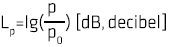
where p is the effective sound pressure [μbar]
pe is the audibility threshold at 1,000 Hz, p0=2.10-4 μbar as reference sound pressure
Frequency f refers to the number of vibrations a sound source generates per second and corresponds to the “tone pitch” as concluded from the auditory impression.
Sound Power and Sound Power Level
Sound power P of a noise generator describes the whole scope of the acoustic radiation and should be taken into account as a machine parameter. Contrary to sound pressure, sound power is independent from the measuring distance to the sound source.
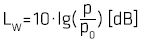
where p is the sound power of the sound source [W]
pe is the reference power for airborne noise, P0=10-12 W
Sound Spectrum
The sound spectrum shows the level distribution within the corresponding frequency range. Here, the sound power or sound pressure levels are defined in connecting frequency bands, for example in octave bands. The usual frequency range for octave band spectrums for positive displacement blowers/screw (-type) compressors is:
Octave mid-band frequencies
31.5 63 125 250 500 1,000 2,000 4,000 8,000 Hz
Evaluation of Sound Pressure Levels (“A”-Weighting)
Frequencies from 16 to 16,000 Hz are audible to the human ear, but the greatest auditory sensitivity is between 1,000 and 4,000 Hz, that is, high sounds above 4,000 Hz and deep sounds below 1,000 Hz are perceived as quieter than sounds with a medium frequency, where the sound pressure remains the same.
Further, the frequency-dependent sensitivity of the human ear is considered in a variety of ways, for instance, in the case of sound measurements, filter curves stored on measuring devices within the sound are used. The main international classification for evaluating sound pressure levels is the so-called “A-curve”. “A-weighted” sound power and sound pressure levels are indicated in dB(A).
| Octave mid-band frequency Hz |
Designation i of the octave |
Weighting f dB |
| 31.5 |
1 |
-39.4 |
| 63 |
2 |
-26.2 |
| 125 |
3 |
-16.1 |
| 250 |
4 |
-8.6 |
| 500 |
5 |
-3.2 |
| 1000 |
6 |
0 |
| 2000 |
7 |
+1.2 |
| 4000 |
8 |
+1.0 |
| 8000 |
9 |
-1.1 |
Sound Measurement: Measured Variables
Standard to be Applied
The DIN 45635 specifies the elementary principles for sound measurements of machines in accordance with the enveloping surface method. This specifies a standardized process for establishing the noise radiated by the machines into the surrounding environment (sound power): as part of the enveloping surface process, the sound power level is measured from the sound pressure level determined over a measurement surface.
Measurement Surface – Sound Pressure Level
To measure sound according to the DIN 45635 standard, the level of sound pressure is defined with the help of a sound level measuring device along notional measuring surface S which surrounds the machine, for example in the form of a cuboid. This sound pressure level A, assessed over the measuring surface S from a number of measuring points and rectified for foreign noise and measurement-environment effects, is defined as measuring surface sound pressure level Lp(A) and indicated in [dB(A)]. The workshop manuals show the specifications for measuring surface sound pressure levels for blower units, based on a sound measurement according to DIN 45635 at a 1 m distance from the free-field contours of the unit.
Correlation between “A” Sound Power Level LW(A) and Measurement Surface Sound Pressure Level LP(A)
According to DIN 45635, the “A” sound power level LW(A) can be determined as follows: LW(A)=LP(A) +LS [dB(A)] with the measurement surface
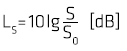
S is the measurement surface contents [m2],
S0 is the reference surface [1 m2]
LS is subtracted for sound-permeable surfaces <1 m2 (e.g. piping), while LS will be added for sound permeable surfaces >1 m2 (e.g. positive displacement blower/screw (-type) compressor units). The measuring surface dimensions of blower and screw (-type) compressor units range between 14 and 20 dB. Size-specific values are also available upon request.
Calculation of Sound Levels
Energetic Level Addition
According to VDI 2571 (“Sound radiation from industrial buildings”), in order to determine noise emissions (influence of sound at a particular distance from the sound source) a total sound pressure level can be determined from the sound pressure levels of the individual sound sources.
The following applies:
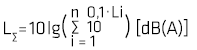
i is the number of sound sources
Li is the individual sound level
For the level addition, it is irelevant whether the level values involve sound power or sound pressure levels, if the reference values match.
For sound sources with equal individual levels, the following can be deduced: LΣ=Li+L+=Li+10 lg i [dB]
i is the number of noise producers [dB]
L+ is the difference to be added to the individual level [dB]
Graphical representation:
.jpg)
Image Credit: Aerzen
Energetic addition of equal sound levels
Example: 4 sound sources with a sound level of 80 dB each create a total level of LΣ = 80 + 6 = 86 dB
For 2 noise producers with varying individual sound levels L1 and L2, the following can be inferred:
LΣ = Li+L+= 10 log .(100,1ΔL+ 1) - ΔL + L1 [dB]
ΔL is the difference between the sound levels, ΔL= L1 - L2
L1 is the higher individual sound level
L2 is the lower individual sound level
Graphical representation:
.jpg)
Image Credit: Aerzen
Energetic addition of two different individual sound levels using the following example: 2 noise sources with L1 = 80 dB and L2 = 76 dB generate a total level of LΣ= 80 + 1.5 = 81.5 dB
Sound Level Decrease as the Distance from the Sound Source Increases
Sound waves are caused by quick increases and decreases in ambient air pressure. As the sound pressure moves further away from the noise source, it changes accordingly. The sound level decrease is minimal in the near field of a sound source. For simple and idealized cases, the values given below can be applied for larger distances (e.g. in free field) for the point sound source (small compared to the distance):
Level decrease for each doubling of the distance: ΔL ≅ 6 dB
.jpg)
r is the distance from the sound source [m]
r0 is the reference distance, r0 = 1 m
VDI-guidelines VDI 2571 “Sound radiation from industrial buildings” and VDI 2714 “Outdoor sound propagation” contain more precise data to determine the level decrease, with due consideration of environmental damping influences, reflection, etc.
Calculation of the Sound Pressure Level in an Installation Room
The acoustic properties of the room itself and the radiated sound power levels of the installed machines determine the sound pressure level within an installation room. Acceding to VDI-guideline 2571 (“Sound radiation from industrial buildings”), the following is relevant for calculating the mean sound pressure level in the room:
.jpg)
LW(A) is the sound power level of all machines in the room [dB(A)]
T is the reverberation period [s]
V: room volume [m3]
Notes
- Calculation of the sound power levels from established individual sound pressure levels and the associated measurement surface levels, see Section 3.3.
- Determination of the total sound power level LW(A) from the individual sound power levels, see Section 4.1.
- Experiential values for T: approximately 2 seconds for traditional factory halls, approximately 4 seconds for large, reverberant rooms, approximately 1 second. for small rooms with highly sound-absorbent limit surfaces
Note: In practice, the sound levels can deviate from the calculated level value at individual points of the installation room (e.g. through screening, sound reflection, etc.)
AERselect Calculation Tool
Users can download the new AERselect calculation tool, which will enable them to perform acoustic calculations.

This information has been sourced, reviewed and adapted from materials provided by Aerzen Machines Ltd.
For more information on this source, please visit Aerzen Machines Ltd.