Sponsored by PerkinElmerReviewed by Maria OsipovaAug 30 2022
All materials, with some exceptions, expand when they are heated. However, the amount of expansion per degree change in temperature varies depending on the substance. Since structures are made up of numerous materials, such as electronics, machines, satellites, buildings, or bridges, they experience tension between materials when cooled or heated.
This stress may cause failure if they were not intended to handle variances in expansion. A TMA is a quick approach to measuring the expansion of a sample in terms of temperature.
The TMA 4000 thermomechanical analyzer (TMA) is designed to precisely measure small modifications in a sample’s dimensions while it is warmed over a predetermined temperature range (Figure 1).
It is a lab analyzer with a tiny tabletop footprint but huge potential for easily and precisely evaluating the coefficient of thermal expansion (CTE). It combines several elements to improve its simplicity of use while also increasing accuracy and sensitivity.
The sample is kept in a furnace enclosure that uses closed-loop temperature control to keep the temperature within a few tenths of a degree (Figure 2).
A fused quartz platform supports the sample, and a position sensor connected to a fused quartz probe, whose weight is mitigated by a buoyancy float and trimmed using a force transducer, tracks its height.
The quartz probe, quartz platform, and sample enlarge as the furnace heats up. As the expansion of the probe and platform cancel each other out, the output of the position sensor can be regarded as a direct measure of the expansion of the sample alone. The buoyancy float dampens external vibration and shields the quartz during sample loading from fracture.
In reality, the TMA technician merely zeroes the sensor’s position with the probe on the level, elevates the probe, sets the sample on the platform, drops the probe onto the sample, elevates the furnace around the sample, and begins the temperature program. The generated record depicts the sample’s expansion as the temperature changes.
Theory
The TMA monitors the sample’s expansion as a function of its temperature. As a result, the primary objective is a plot of sample height vs. temperature. The growth of the sample is a linear function of temperature across a suitably narrow range of temperatures.
As a result, the slope of the expansion curve throughout the temperature range of concern can also be reported.
If the expansion rate is relatively linear, the sample can be equilibrated at T1, its height measured in the TMA, then heated using the TMA temperature program to another temperature T2, equilibrated, the height recorded, and then the expansion rate and the expansivity calculated as (represented by convention as alpha):
.jpg) ,
,
Where L0 represents the original sample height at 20 °C, ΔT represents the change in length (height), and ΔT is the temperature difference between the two equilibration temperatures. This alpha represents the average coefficient of expansion (CTE) for this temperature range.
This CTE can also be determined from scanning data at a suitable slow scanning rate (after giving time for scanning equilibrium condition) by choosing the coefficient of thermal expansion item on the menu in the software and then entering the two temperatures defining the temperature region over which the CTE is to be determined.
Temperatures often range from 10 to 40 degrees (Figure 3). Most facilities that use a TMA follow this technique.
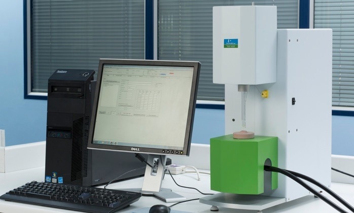
Figure 1. TMA 4000. Image Credit: PerkinElmer
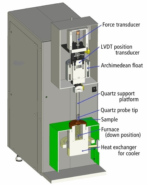
Figure 2. TMA 4000 cross section diagram showing functional components. Image Credit: PerkinElmer
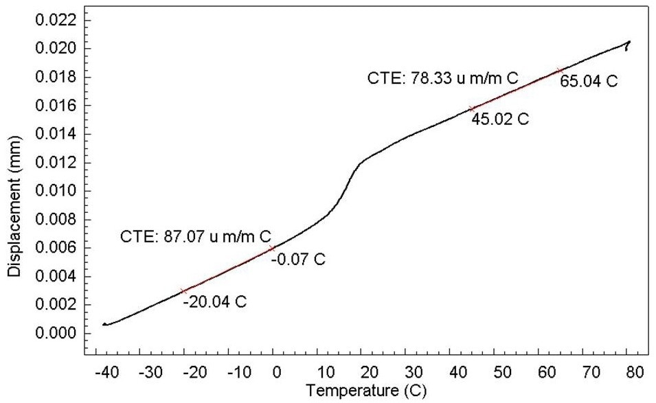
Figure 3. Determination of CTE of PTFE. Image Credit: PerkinElmer
For the broader case of presenting CTE as a function of temperature throughout a wide temperature range:
.jpg)
where .jpg) represents the slope of the expansion curve at temperature T, and L0 represents the initial sample height. As the slope is unlikely to remain consistent over a wide temperature range, alpha is given as a polynomial in powers of temperature. The CTE data is generated by the TMA 4000 in order to determine the polynomial factors.
represents the slope of the expansion curve at temperature T, and L0 represents the initial sample height. As the slope is unlikely to remain consistent over a wide temperature range, alpha is given as a polynomial in powers of temperature. The CTE data is generated by the TMA 4000 in order to determine the polynomial factors.
Experimental Variables
Precise CTE data necessitates the use of a precision TMA, but it also necessitates good experimental procedure.
Outlined below are some of the factors that should be considered when handling samples and developing methods.
Sample Height
In a broad sense, the larger the expanding length, the greater the length change signal and the greater the CTE accuracy. As a benchmark, a sample height of 10 mm is suggested. Due to the LVDT’s broad range and the furnace’s height (40 mm), the TMA 4000 can accept samples up to 12 or 22 mm in height, based on the probe type used.
Sample Shape
The ultimate sample would have a very flat top and bottom so that any load applied to the sample by the probe is distributed across a large enough surface area to prevent sample distortion. Correct CTE readings can only be achieved if the sample does not distort as a result of softening during the experiment.
Of course, valid CTE readings can be obtained from any shaped sample as long as the sample geometry remains constant. Due to the LVDT’s great sensitivity and the viscous damping of the float suspension, extremely light force may be provided without causing noise due to the surrounding vibration.
Sample Orientation
Samples will not necessarily grow isotropically. Fibers, for instance, will expand completely differently along compared to across the fiber; and a circuit component could use a fiber filler to constrain the expansion within one axis or within one plane and force volumetric expansion in the third direction. To characterize such a sample, the expansion along each of the three axes needs to be measured.
Probe Force
The force exerted by the probe on the sample is within the control of the TMA operator. The force can be continually adjusted in either the up or down direction. On average, a low force is required if the sample is expected to soften. If the sample is not anticipated to soften within the temperature range being tested, a stronger probe force is required.
Purge Gas
Usually, the purge gas is nitrogen or, when there is no threat of oxidation, air. The standard purge rate is 20 cc/minute, but this rate is not crucial. Due to its higher thermoconductivity, helium is an even superior purge gas. The sample adjusts quicker with helium, allowing for faster scan speeds. The TMA 4000, on the other hand, was built and optimized for usage with nitrogen, which is far less expensive.
Heating Rate and Equilibration Time
The CTE measurement is based on the height difference between the two temperatures, and for that computation to be precise — the sample and thermocouple average temperatures should be very near to each other.
This is best accomplished by allowing for complete equilibration after loading the sample and by permitting appropriate time (and temperature) after commencing the scanning section before utilizing the data for the CTE estimation.
The extent of the equilibration period is determined by the sample size, how effectively the sample is thermally connected to the quartz platform, the interior thermal conductivity of the sample, the furnace temperature, and the purge type. One method for determining how much time is needed is to heat to a new isotherm and observe how long it takes for the signal to become stable.
Procedures
Sample Preparation
The sample for CTE measurement must be cut so that the top and bottom surfaces are flat and parallel. It should not be any thicker side-to-side than is required to stand properly on the platform, and it must not have any burrs that hold the sample or impinge on the probe.
The preparation method should not put tension on the sample or stress that could be released by heating, nor should it raise the sample’s temperature enough to create a physical alteration. For plastics, a razor knife may suffice, although a lapidary system may be necessary for ceramics.
Temperature Calibration
With its built-in digital rectification, the thermocouple enables precise temperature readings and analysis. The primary reason for temperature calibration is to compensate for the difference in temperature that arises as the system is heated between the thermocouple tip and the average temperature of the sample.
This change will be insignificant for a thin film or fiber and hardly noticeable (at moderate scan speeds) for a 1 mm high solid that is in good contact with the furnace tube floor.
By inserting a tiny piece of a clear melting standard between both the probe and the platform and then running the temperature program that users would use for samples, anyone can simply examine the difference in temperature between the tip of the thermocouple and the platform bottom. This is the foundation for temperature calibration.
Length Calibration
The length calibration is done during setup and is unaffected by any operational conditions. It is simple to check by evaluating the actual height of a material disc that has been separately measured with a micrometer.
The length change of a calibration sample (aluminum samples provided) can be measured using the temperature program and experimental circumstances that will be utilized to run tests.
This method has the benefit of adjusting for some flaws as well as rectifying fused quartz expansion. This procedure is most effective when the standard sample strongly matches the samples to be tested.
Baseline Subtraction
It is not required to subtract a baseline when samples are performed using the expansion probe and properly modest scanning speeds. To verify this, the user simply needs to run a no-sample baseline under standard conditions and compare the displacement to that of a typical sample.
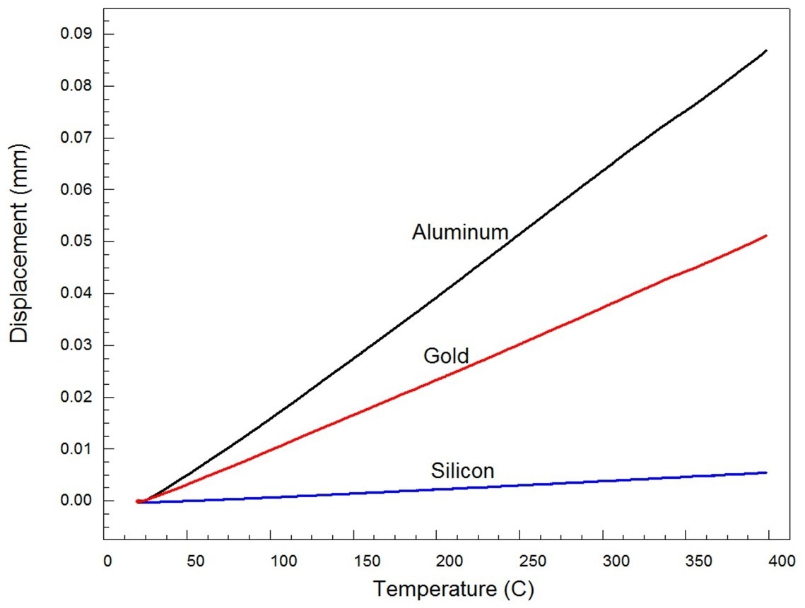
Figure 4. Expansion of pure elemental standards aluminum, gold, and silicon. Image Credit: PerkinElmer
When performing CTE estimates, a baseline should be deducted from the expansion curve if the sample is enclosed in a capsule, seated on a pedestal, in a dilatometer, or suspended in extension by clips. In addition, when higher heating rates than those mentioned above are employed, eliminating a baseline minimizes system error caused by temperature gradients.
Results
Running reference samples and comparing the data to the results provided by well reputable labs is one technique to evaluate the abilities of a novel TMA. Standard Reference Material 731-L1, Borosilicate Glass, is a major reference for thermal expansion developed by the National Institute of Standards and Technology (NIST).
The other substances examined were pure metals: gold, silver, and aluminum — all of which had previously been examined by England’s National Physical Laboratory. These are PerkinElmer’s basic thermal analysis melting point temperature calibration materials.
The images below depict the raw data for the CTE of fused quartz, which has been rectified in the table. The testing circumstances are realistic, with a heating rate of 5 °C/minute and a nitrogen purge gas. The sample size ranged from 5 to 10 mm.
The expansion statistics for the three pure materials are shown in Figure 4.
Figure 5 depicts the NIST borosilicate glass standard expansion information as well as the TMA 4000 expansion information.
Table 1 compares TMA findings to NIST and NPL data to summarize the values of CTE at 227 °C for four reference materials. The glass plot depicts NIST and TMA 4000 data versus temperature.
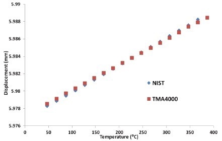
Figure 5. Expansion of Borosilicate glass. Image Credit: PerkinElmer
Table 1. CTE Results using standard materials. Source: PerkinElmer
| Material |
CTE (um/mC) at 227 °C |
| TMA 4000 |
NPL/NIST Value |
| Aluminum (not same material) |
25.08 |
26.4 |
| Silver |
19.15 |
20.6 |
| Gold |
15.24 |
15.4 |
| Silicon |
3.2 |
3.5 |
| Borosilicate glass |
4.5 |
4.33 |
Summary
The results indicate that the TMA 4000 can precisely estimate the coefficient of thermal expansion of numerous well-characterized materials.
Due to its low CTE and poor thermal conductivity, borosilicate glass is a particularly difficult sample. The quality of the measurement electronics, the design of the probe/stage measuring system, and the accurate thermostating of the LVDT position sensor all contribute to the TMA 4000’s capability to achieve these results.
Minor vibrations in the tabletop could otherwise cause noise in the sensitive position sensor; therefore, using a damped suspension system is critical.
When evaluating the dimensional variations of low-expansion, undersized samples commonly seen in the electronics sector, this level of precision and sensitivity is critical.
References
- Kaye and Laby Online, Section 2.3.5 Version 1.1 updated 2 December 2010 (On-line physical constant database maintained by National Physical Laboratory)

This information has been sourced, reviewed and adapted from materials provided by PerkinElmer.
For more information on this source, please visit PerkinElmer.