This article presents a study conducted by DÜRR NDT GmbH & Co. KG. The study was inspired by a 2016 paper authored by Steven Mango, which examined a similar topic, providing the following conclusions and recommendations1:
- Lead screens have a significant impact on image intensity (pixel value) in gamma exposures, particularly with higher-energy isotopes like Iridium-192. Thin lead front screens have a greater intensification effect than thick lead front screens, with maximum intensification at 0.125 mm thickness.
This intensification is also exhibited using rear lead screens. However, thicker screens provide more intensification than thinner screens, with maximum intensification observed at 0.250 mm thickness. Copper screens do not create any intensification effect.
- In front screens, this intensification is desirable because it leads to an increase in image signal-to-noise ratio (SNR). For rear screens, it is undesirable as it could result in reduced basic spatial resolution (SRb) since it primarily amplifies low-energy scatter radiation that is present on the rear of the imaging plate.
- It was determined that the rear lead screen should not be in direct contact with the imaging plate, and an extra shielding of copper (between 0.125 mm and 0.250 mm) or steel should be positioned between them for this undesirable fluorescence produced by the lead screen to be absorbed.
Aims of the Study
The study aimed to confirm the main findings of the aforementioned paper, as described above.1 The study also aimed to quantitatively measure the effects of various metallic screen types and thicknesses on image quality by measuring basic spatial resolution (SRb) and signal-to-noise ratio (SNR), in addition to the associated pixel value.
Lastly, the study was intended to propose practical recommendations for employing metallic screens with Iridium-192 based on the result data.
Theory
While the detailed physics involved in the interaction between X-Ray radiation and matter is beyond the scope of the study, it is vital to have a high-level understanding of why screens may be employed in digital radiography. The above-mentioned paper explores this topic in greater detail and provides a useful additional introduction.1
Scattered Radiation
When a photon with enough energy collides with an orbital electron of an atom within a given material, the electron is ejected from the atom, and the photon scatters in a different direction with lower energy.
Since imaging plates have a higher absorption efficiency at lower radiation energies, these scattered photons are of interest. Low-energy photons that travel in an altered direction (relative to the primary X-Ray beam) can have a significant impact on image quality.
Typically, thin lead screens are employed on both the front and back of the imaging plate for these undesirable photons to be absorbed.
Fluorescence
Fluorescence, also referred to as the photoelectric effect, occurs when the incoming photon is completely absorbed by the atom during a collision with the electron. This photon is subsequently ejected and becomes a “photoelectron”.
Lower energy photons are created when an electron drops from a higher shell to fill the gap in the lower shell formed by the ejected electron.
The difference in energy level between the two electron shells (characteristic of the given element) determines the energy of these photons. The imaging plate readily absorbs this low-energy radiation.
For the X-Ray energy levels that are generally used in industrial radiography, the required energy to eject electrons from the innermost shell (which are the most strongly bound electrons) is most important.
The “K-edge” is the term used to describe the energy at which this ejection begins to occur and varies depending on the material. As the incoming X-Ray energy exceeds the K-edge, the likelihood of this photoelectric absorption occurring decreases.
The K-edge of lead is approximately 88 keV (while that of copper is 9 keV), which means this fluorescence is expected when utilizing lead screens in industrial radiography.
Methodology
Exposure Setup
To accurately measure the impact of various screen thicknesses and types on image quality, it is required that any parameter that could potentially alter the image quality is kept constant, and the screen setup is the only variable that changes.
The setup employed in this study is detailed in Figure 1 and Table 1. The following considerations were made to further ensure reliable data:
- All exposures were obtained in one day (over 9 hours) to reduce the effect of reducing isotope source activity.
- The same equipment, including screens, computed radiography scanner, imaging plate, and gamma source, as well as location, were utilized for the whole experiment.
- The scanning of the imaging plate took place immediately after the exposure and was scanned in the same orientation for each scan.
- A lower-sensitivity imaging plate (HD-IP) was employed with a longer exposure time (compared to a high-sensitivity IP and short exposure time) to reduce the effect of any minor variations in exposure time (i.e. dosage).
- The object was positioned directly on top of a 16.3 mm wood board to facilitate the scatter radiation reaching the rear of the imaging plate.
- The stackup from the source-side was as follows: Pb → Cu → Object → IP → Cu → Pb
Table 1. Exposure setup. Source: DÜRR NDT GmbH & Co. KG
| Radiation Source |
| Type |
Iridium-192 (with collimator) |
| Activity |
25.19 Ci |
| Focal Size |
3 mm |
| Object |
| Material |
Stainless Steel (SS304) |
| Thickness |
10 mm |
| Setup |
| Imaging Plate |
10x24 cm HD-IP |
| Source-to-Object Distance |
300 mm |
| Exposure Time |
4:00 min |
| Scanner |
| Type |
DÜRR NDT HD-CR 35 NDT |
| Laser Size |
25 μm |
| Reading Pitch |
25 μm |
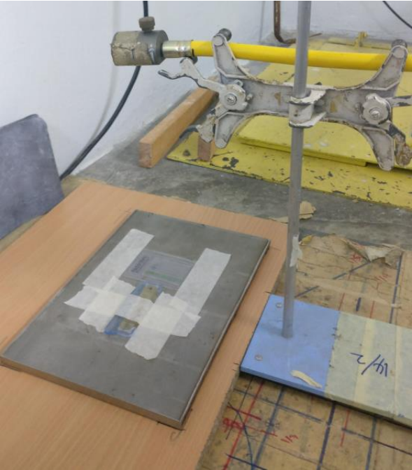
Figure 1. Exposure setup. Image Credit: DÜRR NDT GmbH & Co. KG
Image Quality Measurement
A single exposure was carried out for each screen setup. The DÜRR NDT D-Tect image analysis software was employed to measure the following image quality metrics:
- Signal-to-Noise Ratio (SNR): The mean value of five different areas was calculated, each area with dimensions of 100 x 100 pixels.
- Pixel Value: The mean value was taken for the same five areas as the SNR measurements.
- Basic Spatial Resolution (SRb): This is measured using a source-side duplex wire IQI in accordance with ISO 19232-5.2 The modulation (dip) for duplex wire pairs 1D to 5D was measured over the width of the IQI (651-pixel lines) and the mean of these five values was taken as the measure of the image basic spatial resolution
Please note that the 2nd-order interpolation method was not employed since it consistently produced incorrect results when carried out with only five duplex wire pairs.
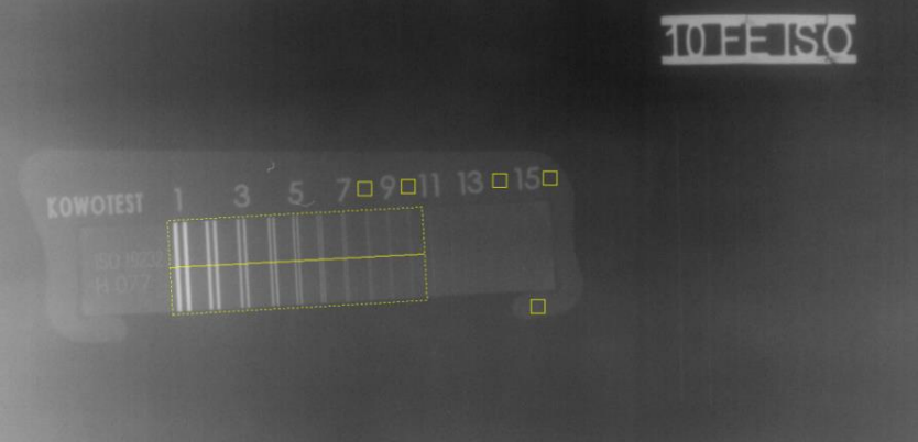
Figure 2. Cropped digital X-ray image from D-Tect software showing the areas of measurement. Image Credit: DÜRR NDT GmbH & Co. KG
Results
All result data was normalized to an exposure with no front or rear screens. All graphs were plotted using the same y-axis range to enable the relative effects of each screen configuration to be easily visually compared. Table 2 displays the numerical value for each plotted data point.
Front Screen Only
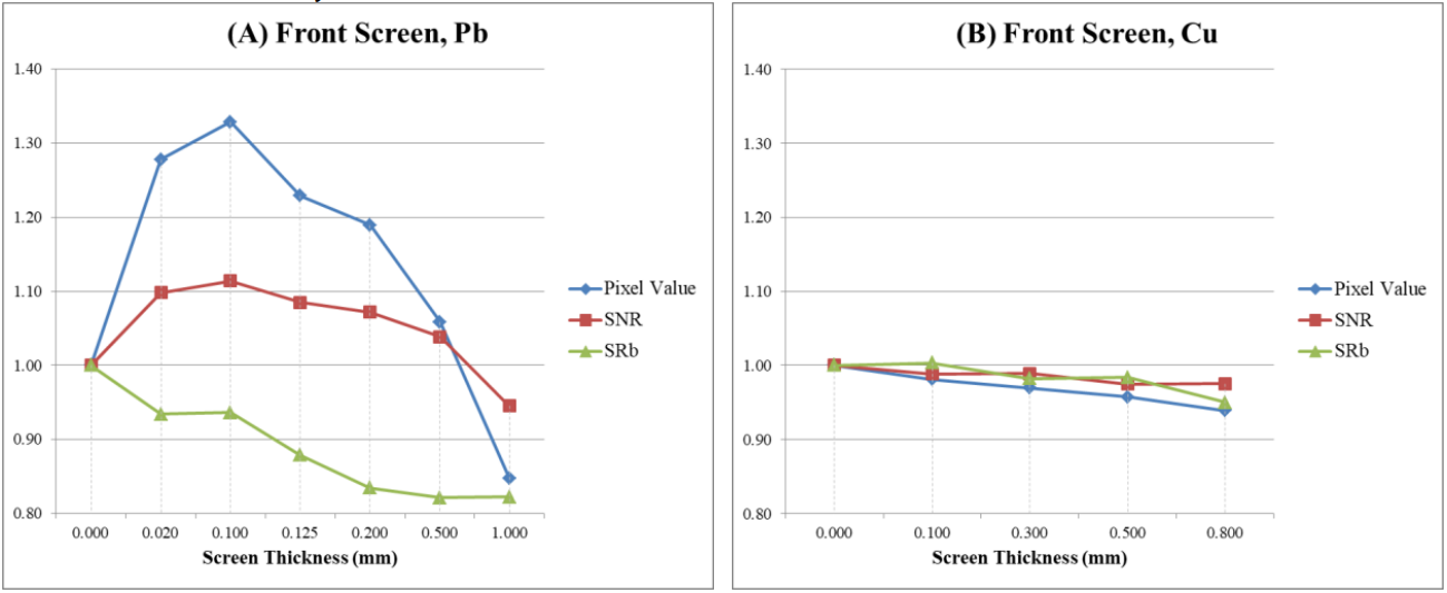
Figure 3. Effects of lead (A) and copper (B) front screen thickness on image quality. Image Credit: DÜRR NDT GmbH & Co. KG
It was observed that a higher pixel value corresponds to a higher image signal-to-noise ratio (SNR), in a non-linear correlation.
Only lead screens were found to provide intensification, as copper front screens do not result in any intensification effect and instead only reduce the incoming radiation.
The intensification effect caused by the lead screen increased until a maximum was reached at 0.100 mm thickness. The incoming radiation began to reduce at a lead screen thickness between 0.500 mm and 1 mm.
Basic spatial resolution (SRb) appeared to decrease with lead screens until the intensification effect was no longer present. This can be interpolated to take place at slightly above 0.500 mm lead thickness.
Copper screens offered significantly less degradation in basic spatial resolution (SRb), relative to lead screens.
Rear Screen Only
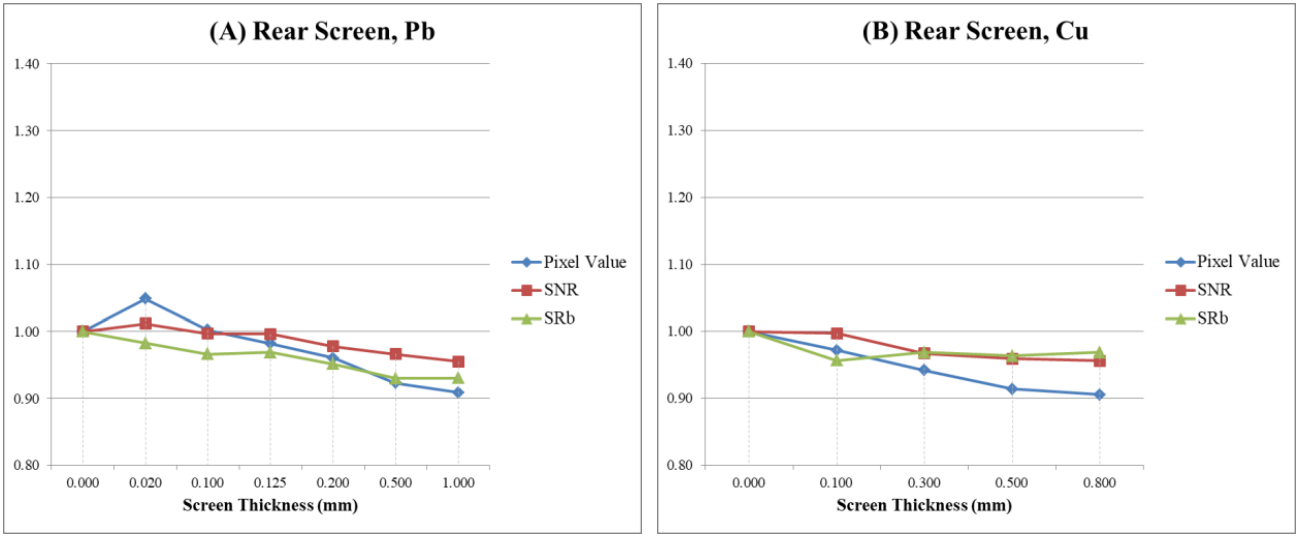
Figure 4. Effects of lead (A) and copper (B) rear screen thickness on image quality. Image Credit: DÜRR NDT GmbH & Co. KG
Like with front screens, only lead rear screens cause the intensification effect and not copper screens. However, the effect was considerably less for rear screens than for front screens. Both 0.020 mm and 0.100 mm lead screens offered marginal intensification, while thicknesses greater than this attenuated the radiation.
As expected, there was a strong correlation between the pixel value and the signal-to-noise ratio (SNR).
Both copper and lead screens did not appear to improve the SRb, but the degradation was much less with copper.
Front and Rear Screen
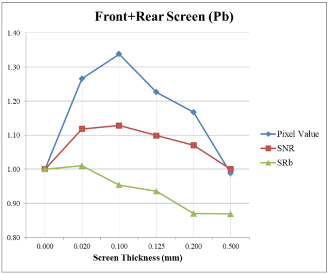
Figure 5. Effects of front and rear lead screen thickness on image quality. Image Credit: DÜRR NDT GmbH & Co. KG
The overall results are what would be expected if the results for the front lead screen (Figure 3A) and rear lead screen (Figure 4A) were combined.
Basic spatial resolution (SRb) is improved when a rear lead screen is also used, compared to using only a front lead screen.
Practical Screen Combinations
As a 0.100 mm lead screen was found to create the greatest intensification effect, the use of this particular thickness with different copper screen thicknesses was studied for both the front and rear of the imaging plate.
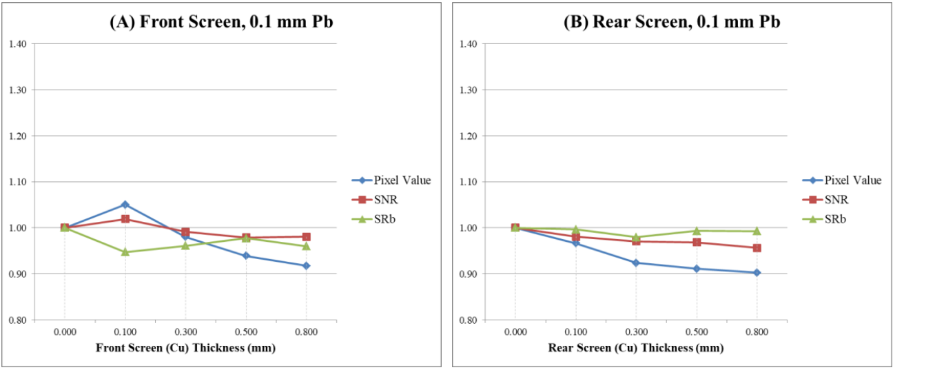 Figure 6. Effects of varying the front screen (A) and rear screen (B) copper thickness on image quality. A 0.100 mm lead screen is used in both cases. Note: The 0.000 mm Cu thickness data corresponds to the no screen exposure. Image Credit: DÜRR NDT GmbH & Co. KG
Compared to using only a lead screen, using a copper screen in between the lead screen and the imaging plate improved the basic spatial resolution (SRb). This was the case for both the front and rear of the imaging plate.
All the fluorescence generated by the 0.100 mm front lead screen was absorbed by copper screens with a thickness of 0.300 mm and above.
Employing a rear copper screen thickness of 0.300 mm together with a 0.100 mm lead screen allows most of the radiation incident on the rear of the imaging plate to be attenuated (i.e. pixel value only slightly decreases for copper screen thicknesses above this).
Data
Table 2. Complete result dataset (Note: Empty cells correspond to ‘no screen’). Source: DÜRR NDT GmbH & Co. KG
| Figure |
Front Screen (mm) |
Rear Screen (mm) |
Pixel Value |
SNR |
SRb |
| Pb |
Cu |
Pb |
Cu |
| - |
|
|
|
|
1.00 |
1.00 |
1.00 |
| 3A |
0.020 |
|
|
|
1.28 |
1.10 |
0.93 |
| 0.100 |
|
|
|
1.33 |
1.11 |
0.94 |
| 0.125 |
|
|
|
1.23 |
1.08 |
0.88 |
| 0.200 |
|
|
|
1.19 |
1.07 |
0.83 |
| 0.500 |
|
|
|
1.06 |
1.04 |
0.82 |
| 1.000 |
|
|
|
0.85 |
0.95 |
0.82 |
| 3B |
|
0.100 |
|
|
0.98 |
0.99 |
1.00 |
| |
0.300 |
|
|
0.97 |
0.99 |
0.98 |
| |
0.500 |
|
|
0.96 |
0.98 |
0.98 |
| |
0.800 |
|
|
0.94 |
0.98 |
0.95 |
| 4A |
|
|
0.020 |
|
1.05 |
1.01 |
0.98 |
| |
|
0.100 |
|
1.00 |
1.00 |
0.97 |
| |
|
0.125 |
|
0.98 |
1.00 |
0.97 |
| |
|
0.200 |
|
0.96 |
0.98 |
0.95 |
| |
|
0.500 |
|
0.92 |
0.97 |
0.93 |
| |
|
1.000 |
|
0.91 |
0.96 |
0.93 |
| 4B |
|
|
|
0.100 |
0.97 |
1.00 |
0.96 |
| |
|
|
0.300 |
0.94 |
0.97 |
0.97 |
| |
|
|
0.500 |
0.91 |
0.96 |
0.96 |
| |
|
|
0.800 |
0.91 |
0.96 |
0.97 |
| 5 |
0.020 |
|
0.020 |
|
1.27 |
1.12 |
1.01 |
| 0.100 |
|
0.100 |
|
1.34 |
1.13 |
0.95 |
| 0.125 |
|
0.125 |
|
1.23 |
1.10 |
0.94 |
| 0.200 |
|
0.200 |
|
1.17 |
1.07 |
0.87 |
| 0.500 |
|
0.500 |
|
0.99 |
1.00 |
0.87 |
| 6A |
0.100 |
0.100 |
|
|
1.05 |
1.02 |
0.95 |
| 0.100 |
0.300 |
|
|
0.98 |
0.99 |
0.96 |
| 0.100 |
0.500 |
|
|
0.94 |
0.98 |
0.98 |
| 0.100 |
0.800 |
|
|
0.92 |
0.98 |
0.96 |
| 6B |
|
|
0.100 |
0.100 |
0.97 |
0.98 |
1.00 |
| |
|
0.100 |
0.300 |
0.92 |
0.97 |
0.98 |
| |
|
0.100 |
0.500 |
0.91 |
0.97 |
0.99 |
| |
|
0.100 |
0.800 |
0.90 |
0.96 |
0.99 |
Conclusions
The data collected in this study is heavily dependent on the exposure setup, which means that the following findings may not apply to every inspection scenario. However, these findings should be a useful starting point when using Iridium-192:
- A 0.100 mm front lead screen provides the greatest intensification effect (more than a 30% increase in pixel value, resulting in more than a 10% increase in SNR).
- There is a trade-off when using both a lead and copper front screen:
- The advantage of increased SNR caused by the intensifying effect (fluorescence) of the lead screen is nearly eliminated.
- However, a copper screen offers a slightly sharper image than using a lead screen alone.
- Employing a 0.100 mm lead screen together with a 0.300 mm copper screen on the rear of the imaging plate delivers approximately the same amount of backscatter attenuation as a single 0.500 mm lead screen. This combination also offers a sharper image than using a lead screen alone.
For radiation safety reasons, it is always desirable to minimize the exposure time, especially when using a portable gamma isotope such as Iridium-192. Using a 0.100 mm front lead screen is a straightforward way to achieve this while still allowing some flexibility of the imaging plate to inspect curved objects.
The overall findings of this study largely agree with those of the above-mentioned paper.1 However, the study detailed in this article measured significantly lower rear lead screen intensification, while increasing the rear lead screen thickness did not increase intensification, but did attenuate the radiation.
Future Work
Basic spatial resolution (SRb) was observed to be less in nearly all screen setups than when using no screens.
It was not investigated whether increasing the dose could have compensated for this minor reduction in sharpness caused by the use of screens. A further experiment could examine whether using, for example, a copper front screen with an extended exposure time improves the image sharpness and to what extent.
Any future similar studies should use averaged data from multiple identical exposures to enhance the accuracy of the results.
Acknowledgments
Produced from materials originally authored by DÜRR NDT GmbH & Co. KG, Germany.
References
- Mango, S., Practical Considerations and Effects of Metallic Screen Fluorescence and Backscatter Control in Gamma Computed Radiography, 19th World Conference on NonDestructive Testing, Munich, Germany, 2016
- Non-destructive testing – Image quality of radiographs, Part 5: Determination of the image unsharpness and basic spatial resolution value using duplex wire-type image quality indicators, ISO 19232-5, 3rd ed., Aug 2018

This information has been sourced, reviewed and adapted from materials provided by DÜRR NDT GmbH & Co. KG.
For more information on this source, please visit DÜRR NDT GmbH & Co. KG.