Flash-radiography (FR) is a form of radiography that does not involve intermediate data carriers such as films and storage plates. FR quickly creates a quick image and provides a low cost of testing, as well as the capacity for multi-angle real-time monitoring of internal defects of the objects.
In film radiography, if the relative photometric density exceeds four, then the snapshots are practically unreadable, making their digitization challenging. Current film-free technologies do not face this challenge and deliver results in a digital form without special digitizing systems being required.
Digital data comprises radiation images of internal defects, expanding the flaw-detection possibilities and reducing the cost of testing.
FR utilizes portable X-Ray television, i.e., observing X-Ray testing results on a monitor screen. This enables internal defects to be examined from different angles.
FR with digital solid-state transducers is the most prospective one with sensitivity up to 0.1% of the thickness of the sample metal at a resolution greater than 10 pairs of lines per mm.
The application of small-size movable solid-state transducers introduces new technological abilities. These transducers may be located and moved in the zones where the positioning of storage plates and film holders is impossible.
Radiation testing is a common form of non-destructive testing (NDT) of quality, material, and parts. It can be employed to test parts of any geometry, shape, or material.
Radiation techniques are preferred when testing the quality of brazed and welded joints, in addition to mastering the number of process solutions due to illustrative results. This technique is also employed to validate other NDT techniques.
Recently, there have been significant qualitative changes that expand the potential of radiation non-destructive testing.
These changes are a result of the introduction of new multi-element semiconductor radiation image detectors, in addition to the intensive implementation of means for processing, producing, and analyzing digital images, which are illustrative and easy for archiving and electronic transmission.
These detectors utilize electron means and transform ionizing irradiation, passing through the object under examination and containing information regarding the object’s internal defects, into an electric signals package.
Subsequently, the signals are digitized, processed, and employed to form a digital image of the object that is being examined. The digital image (DI) can be observed directly in real-time. This radiation testing technique without intermediate carriers of information is called flash radiography (FR).
Essentially, it is portable X-Ray television with an electron record of information that can be provided to a customer, put on the Internet, archived, and stored on memory cards without further digitalizing and decoding being necessary.
A characteristic feature of FR is the lack of intermediate carriers of information such as radiographic films and semiconductor (SC) store plates with photo-stimulated memory.
In common technologies with intermediate carriers of information, adjusting the mode demands multiple exposures, highlighting, processing, and costly devices to digitize and read information.
This means that the absence of intermediate carriers of information (such as films and semiconductor plates) increases efficiency and significantly reduces the cost of quality testing.
Methods for Acquiring Digital Images
Examining the internal defects of an object using portable X-Ray television equipment with digital image processing enables principle changes in the technology of non-destructive radiation testing.
In recent years, the frequency of the application of optical and radiation digital images (DI) has increased. This means that software and hardware complexes that are employed to process and digitize X-Ray films and provide digital images find more distribution.
The digital images may also be produced using storage plates instead of X-Ray films. The methods and algorithms of DI processing are the same for the three variants of radiation testing, as displayed in Figures 1-3. This is significant in current radiation flaw detection.
Digital images are usually produced using X-Ray patterns digitization, while occasionally they are produced by processing latent images read from reusable storage plates. The same result can be produced using FR digital detectors without the added expense of intermediate information carriers.
The digital image output of any of these three indicated methods will have a similar interpretation. The results of processing radiography DI are not inferior to the sensitivity and resolving power of the results of the radiographic film received using a film viewer.
The image quality is evaluated using the reference specimen images. On DI, they are similar to the reference specimen images of X-Ray films examined using the film viewer.
There are three technologies (as shown in Figures 1-3) for receiving the DI results of radiation testing in electron form, but the principles of processing and further decoding of these images remain the same.
Figure 1 presents a traditional process for DI production via the digitization of film X-Ray patterns. This technology is common in all areas of industry and requires film cartridges and screens to be prepared.
After inspection, a chemical treatment takes place. This is followed by film drying, using the film viewer to read information, and digitizing the results using the corresponding computer complex.
This technology is primarily used for the compact archiving of NDT results in electron form as well as for the receipt of further information which requires digitization to be obtained.
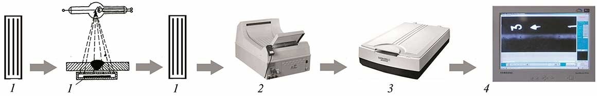
Figure 1. Traditional scheme of radiographic testing with film and digitization of X-ray patterns: (1) cartridge with X-ray film; (2) processing of X-ray film; (3) image scanning; (4) digital image. Image Credit: DÜRR NDT GmbH & Co. KG
Figure 2 presents a scheme of CR technology for digital image production based on storage plates. Compared to the traditional process of DI production as described above, this technology enables multiple uses of an intermediate carrier of information (storage plate).
This speeds up the process but does not reduce the cost as it requires qualified personnel and expensive readout equipment, as well as a substantial amount of time for auxiliary operations.
Frequently, the storage plates have their inherent defects. Eliminating the details of this method’s disadvantages, it is necessary to note the appearance of “sandwich” technology which enables exposing on film and storage plate to take place simultaneously.
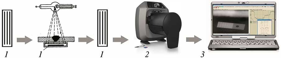
Figure 2. Scheme of inspection using storage plate: (1) cartridge with store plate; (2) read of information from plates; (3) digital image. Image Credit: DÜRR NDT GmbH & Co. KG
Global manufacturers of film, including Fuji, Agfa, and Kodak, kept the way of film replacement with semiconductor multiuse storage plates. Different equipment was developed for this technology realization.
The E. O. Paton Electric Welding Institute has spent a considerable amount of time on the implementation of selenium plates and other intermediate carriers of information.
Technologies that employ reusable carriers of information did not gain ground due to equipment being expensive and the requirement for highly skilled personnel.
Figure 3 displays a scheme of X-Ray technology (flash-radiography) based on solid and fluoroscopic detectors. This is the cheapest and quickest method for the production of a digital image in an e-form, which does not demand processing and reading equipment and the corresponding additional time.
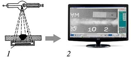
Figure 3. Quick X-ray inspection scheme without intermediate carriers of information: (1) solid flash-transducer; (2) digital image. Image Credit: DÜRR NDT GmbH & Co. KG
Both types of radiation testing without X-Ray films that are presented in Figures 2 and 3 can deliver improved results than that of a digitized image produced using X-Ray film.
The Quality of Digital Images Obtained by Different Methods
The higher the optical density and the more exposure, the more information that the exposed film contains. As a result, a good scanner is required for the digitization of high-density films to ensure that all the available data is collected.
Cheap scanners and common reading devices cannot provide high-quality digitized X-Ray images if their relative optical density exceeds three. All attempts to receive satisfactory DI from the denser films have been unsuccessful.
As a result, if the optical film density lies within the 1.5-2.5 range, then satisfactory DI in the film variant (see Figure 1) is possible. At such values, the digitizer noises do not introduce irreversible distortions in DI. The digitization of film images with 3-3.2 order density has shown unsatisfactory results.
Fine information is difficult to display, such as images of pores smaller than 0.2 mm in diameter, and cracks with small openings are lost. This is a significant limitation of film digitization.
Part of the defects that are detected using a film viewer is not found on DI, which is a major disadvantage of traditional film radiography that is essentially impossible to eliminate in real production.
The technologies that do not involve film, displayed in Figures 2 and 3, do not have this disadvantage as they have a large dynamic range that expands the possibilities of non-destructive testing.
Analyzing DI with the technological schemes of Figures 2 and 3 verified that the detectability of cracks, small pores, and different inclusions in the welded joints provides more information than film.
The technology of Figure 3 is based on solid or optoelectronic transducers and is particularly perspective, offering the possibility (after DI computer processing) to obtain up to 0.1% sensitivity and examine a moving object.
The defect detectability is improved as small moving images are better distinguished by the human eye than they are when static. It is possible to change the inspection direction if the intermediate carriers of information are absent during the inspection on the scheme of Figure 3.
The DI received for the three technologies in Figures 1-3 is easy to archive and webcast. The time consumption and cost of information being received using these technological schemes approximately refer correspondingly to 10:5:1 and 5:20:1, respectively across the three technologies.
The film radiography presented in Figure 1 involves many procedures that are sometimes repeated multiple times to obtain satisfactory results. FR does not require such procedures. Film radiography takes approximately 10 times longer than FR (Figure 3) to obtain the same result.
Using the storage plates requires fewer auxiliary procedures to obtain the same information from the object. This results in the time spent being approximately correlated as 10:5:1.
Regarding the cost, the ratio of 5:20:1 means that during X-Ray technologies in Figures 1 and 2 require the equipment for information reading, highly qualified specialists, and repeated exposures to obtain the same results as FR. The technologies presented in Figures 1 and 3 do not require expensive maintenance.
The numbers 5:20:1 depend on many factors, such as the level of life in each country. For FR, both the cost and time were taken to be 1, while the other techniques (shown in Figures 1 and 2) require more cost 5:20:1 and time 10:5:1.
The exposure at the dentist or fluoroscopy in the hospital is performed for a few seconds, and the image costs a few cents. However, the similar results obtained using technologies presented in Figures 1 and 2 demand significantly more time and are much more costly.
In a short time, detecting the internal defect corrosion damages using portable FR equipment would become mandatory for all oil-and-gas auxiliary pipelines, which currently have almost no control, since ultrasonic testing is low efficiency and X-Ray film testing is expensive.
Figure 4 displays structural schemes of radiation testing image production in electron form for the three above-described technologies. Procedures of these technologies vary in a stage of digital image production, while DI processing is the same for all three schemes. This means that the costs and equipment involved are also different.
A general weakness of the first two technologies with intermediate carriers of information (presented in Figures 1 and 2) is the requirement for re-inspections, sometimes multiple inspections, to determine the optimum values of anode voltage, exposure time, focal distance, and auxiliary procedures.
When working with new unknown objects, an operator typically needs to find the appropriate inspection mode and procedure for the intermediate carrier of information. This is usually performed by repeating all preparatory operations before inspection.
The most significant advantage of the technology presented in Figure 3 is the option to observe image changes during inspection to determine the optimum modes. There is also the possibility of a multi-angle examination of images of any internal defects.
Technologies that employ small, few square centimeters, solid digital electron transducers are of specific interest because they do not have limitations associated with screens, cartridges, and storage plates.
Mobile transducers can move freely over the surface of the object being examined. Such possibilities are included in the diagnostics of widely employed large customs objects which can be of unlimited size.8 Testing these objects using intermediate carriers of information (films, storage plates) is practically unreal.8
Miniature solid transducers may be inserted in structures of various shapes. Images from separate small transducers are merged into one general image of an object of a complex form.
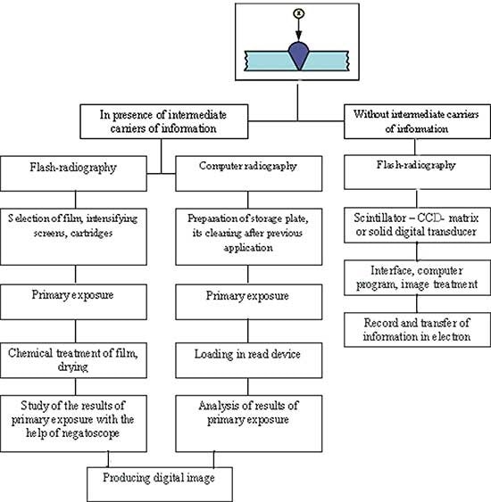
Figure 4. Structural scheme of process procedures for getting the results of radiation testing in electronic form with film (see Figure 1), computer (see Figure 2) and flash-radiography (see Figure 3). Image Credit: DÜRR NDT GmbH & Co. KG
FR enables the varying of key parameters (exposure, focus distance, anode voltage, and current) to observe the changes in the image on the display screen in real time. This minimizes both the time and consumables involved.
Artifacts from screens, films, storage plates, and cartridges in technologies with intermediate carriers of information are hard to remove.
With real-time images, such as that of Figure 3, and the possibility of varying testing mode parameters, the artifacts are easily detected and removed. There are algorithms of electron image operation that provide for the accumulation and extraction of separate fragments in DI.
Equipment for Flash-Radiography
Japan, the US, Russia, and other countries conduct intensive work to improve solid electron transducers; mobile X-Ray television flaw detectors can replace ultrasonic equipment as they offer improved detection capabilities. This will also become the case in other countries.
As a result, the process capabilities of FR must be studied. Many companies manufacture different scintillation panels, and a significant part of these devices is described by Troitskiy et al.3
The E. O. Paton Electric Welding Institute collaborates with the Hamamatsu Photonics company in Japan. Figure 5 presents two principles of design of the solid detectors produced by this company, while Table 1 details the characteristics of some of these.
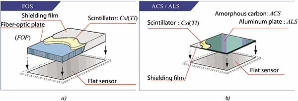
Figure 5. Design variants of flat flaw detectors of Hamamatsu Photonics company: (a) design in which image from screen to sensor is transferred by fiber-optic plate; (b) design with direct positioning of scintillation screen over sensor (CCD-matrix). Image Credit: DÜRR NDT GmbH & Co. KG
Table 1. Characteristics of scintillator panels Csl (Tl) of Hamamatsu company. Source: DÜRR NDT GmbH & Co. KG
| Panel |
Panel type |
Size, mm |
Effective area, mm |
Substrate thickness, mm |
Scintillator thickness, mm |
Light relative output, % |
Contrast transfer function, lp/mm |
| FOS |
J6673 |
50´10 |
47´7 |
3 |
150 |
70 |
10 |
| J6673-01 |
150 |
40 |
| J6677 |
50´50 |
47´47 |
3 |
150 |
70 |
10 |
| J6677-01 |
150 |
40 |
| ACS |
J8734 |
50´50 |
48´48 |
0,5 |
150 |
125 |
10 |
| J8734-01 |
150 |
150 |
| J8977 |
468´468 |
440´440 |
2 |
600 |
250 |
3 |
| ALS |
J8978 |
50´50 |
48´48 |
1 |
150 |
70 |
10 |
| J9857 |
468´468 |
440´440 |
1 |
600 |
150 |
3 |
The following designations are taken in the Table 1: FOS - Fiber Optic Plate with Scintillator; ACS - Amorphous-Carbon Plate with Scintillator; ALS - Aluminum Plate with Scintillator. Light output and contrast transfer function (CTF) were measured with the help of CCD-matrix at 60kV voltage on X-ray tube. Aluminum filter of 1 mm thickness was used.
Many companies in Japan, the US, and Europe produce solid digital transducers for radiation testing problems. Figure 6 illustrates the examination process of pipeline corrosion damage using a solid transducer of DRP 2020 NDT type.9
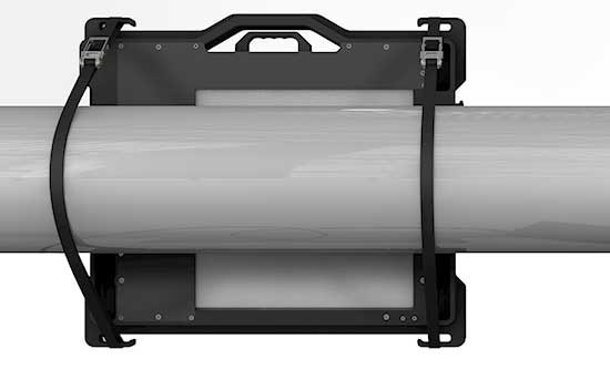
Figure 6. Examination of corrosion damage of pipeline with the help of DRP 2020 NDT. Image Credit: DÜRR NDT GmbH & Co. KG
Table 2. Technical characteristics of digital radiation transducer DRP2020NDT. Source: DÜRR NDT GmbH & Co. KG
| . |
. |
| Size (thickness x width x length), cm |
2.2 ´ 29.5 ´ 36 |
| Weight, kg |
3.7 |
| Power source |
110 – 240 ?, 215 W |
| Temperature range, °? |
10 – 40 |
| Connection to computer |
USB 2.0, LAN |
| Safety class |
IP 65 |
| Active operating zone |
204.8 x 204.8 |
| Digital capacity, bit |
14 or 16 |
The quality of the images is catheterized by specific indices.2,10 These include the following:
- The basic spatial resolution (SRb) is measured using the Duplex IQI (EN 462-5), equaling half of the registered sharpness or effective pixel size;
- The spatial resolution is calculated using the distance of neighboring resolvable elements on the image;
- The spatial frequency is the reverse value to the distance of neighboring resolvable elements on the image, measured in lp per millimeter;
- The image’s fuzziness has a multi-factor origin due to geometry and projector conditions;
- The signal-to-noise ratio (SNR) is influenced by the quality and exposure of the radiation track. This relationship increases as the square root of the area of operating pixels;
- The contrast-to-noise ratio (CNR) is dependent on the relationship between signal-to-noise ratio and the coefficient of absorption of the object material.
The dynamic range is considered to compare the possibilities of various methods of radiation testing. These are the thicknesses of the object available for tolerable analysis on one image. The large dynamic range provides advantages for the technologies displayed in Figures 2 and 3, compared to film radiography.
Typically, a large dynamic range is attained as a result of exposure dose that is limited in film systems by the relative optical density of 3-4. They also are unreadable at larger film densities.
Regarding digital detection systems H&D (without intermediate carriers of information) “exposure”, i.e. information storage, has no limitations caused by computer technologies. Here, the signal-to-noise ratio (SNR) rises as the square root of the dose. It is equivalent to the exposure time or the amount of averaged images.
As a result, the SNR is equal to several thousand, and a high quality of DI is achieved. In practice, these processes are restricted by a contrast sensitivity of 0.1% which corresponds to an SNR of 1000 order.
It is evident that radiation testing without intermediate carriers of information but with elements of scanning and the possibility to change the direction of object irradiation is the future.
Digitally processing images (as shown in Figure 4) comes with reporting procedures, including operations on the evaluation of DI suitability, optical density, measurement of gray intensity, and the determination of sensitivity.
A gray digital scale is typically 16 bites,6 has thousands of tones and the DI histogram shall be approximately in the middle of this scale to avoid under- or overexposure. The central positioning of the histogram offers the possibility of higher quality digital processing by allowing scaling of gray intensity.
Additionally, calibration on size is used to allow the defects to be measured and to carry out other procedures that are atypical for traditional film radiography and ultrasonic testing.
There has been great success with radiation transducers based on shuffle bars with detectors, and these can be applied in customs. All the attempts to use these traducers for welded joint testing have so far been unsuccessful, but these systems are continuously improved.11
X-Ray Mini Technology
An inspection X-Ray system may be developed using mini R-transducers (as shown in Figure 5). This involves the X-Ray transducer being moved over the object's surface as it occurs in ultrasonic testing.
The solid-body transducers eliminate the exposure of large areas and only check small zones where interval defects are expected. Such a mobile FR was used (Figure 7) to examine a testing bench with critical bolts employed to join the power reactors, where internal defects cannot be found by other methods.
Mini R-transducers are recommended for objects like those presented in Figure 7. This variant of FR is termed “X-Ray mini” technology, which can be carried out using any solid-stare transducers, including those displayed in Figure 5.
The mobility of the R-transducer and the R-emitter (isotope, ceramic tube) is used in X-Ray mini technology realizing.
Mini-detectors which are ten times smaller than large-panel ones (as displayed in Figure 6) can easily realize tangential inspection of pipes and stop valves in heat and nuclear engineering.12 X-Ray mini technology will likely be widely applicable to monitor the technical condition of aircraft, lifting, and other dangerous equipment.
The mobility of the R-transducer and emitting source is expanding the capabilities of NDT. As a result, the success of X-Ray mini technology is in its software, with each object having robotics-realized individual programs.
This is conducted per customer request, depending on the technological processes using X-Ray mini technology. The E. O. Paton Electric Welding Institute produces scanners for X-Ray mini and corresponding software.
X-Ray mini testing may have complete or partial automation. FR in the X-Ray mini variant is presented in Figure 8 and was employed to test 1.5 kilometers of main pipeline that was comprised of four pipes of 18 mm diameter at an oxygen plant.
The program can either concurrently examine all pipes or examine each pipe separately. This can be done only using a small solid-state transducer, with its position determined by an operator. Similar radiation testing with intermediate carriers of information requires significantly more money and time than FR.
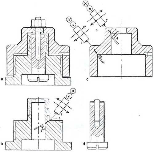
Figure 7. Test bench for bolts of nuclear reactors: (a) total view; (b) plunger; (c) body; (d) bolt being tested; (,2,3) cracks in the plunger and body appearing in testing of high-strength bolts; (4) one; (5) two; (6) three-section solid-state radiation transducers; (7) radiation source (isotope, R – tube). Image Credit: DÜRR NDT GmbH & Co. KG
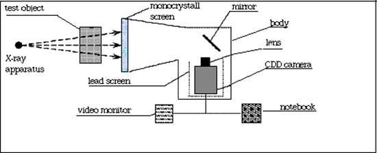
Figure 8. Structure scheme of the portable monocrystalline DI-detector for X-ray television system. Image Credit: DÜRR NDT GmbH & Co. KG
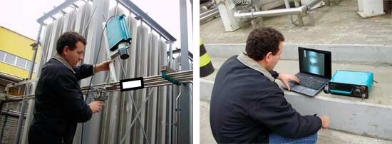
Figure 9. Testing of main pipeline at oxygen plant (a) setting up of X-ray apparatus; (b) monitoring of X-ray mini image. Image Credit: DÜRR NDT GmbH & Co. KG
Conclusions
- Using FR with digital solid transducers is the most perspective technology, providing up to 0.1% of the thickness of inspected metal at a resolution, exceeding 10 lp/mm. This technology is also compatible with film radiography and can be performed on the same X-Ray equipment. All areas of industry need quick and cheap FR.
- The application of small-size movable solid transducers introduces new technological abilities. Solid transducers can be set and moved in the zones where the positioning of cartridges with films and storage plates is infeasible. Digital solid transducers enable new process capabilities for NDT, while not available for other physical methods. X-Ray mini technology is an expanding application of NDT in industry.
- The R-transducer and R-emitter in X-Ray mini technology must move on agreed trajectories, recording at each exposure: coordinates, time, energy, and distance to the object, with the orientation about each other.
- Current equipment facilitates the production of R-detectors and R-emitters of a very small size. X-Ray mini technology expands the capabilities of NDT as for inspection of the objects of any complex geometry, and requires automation of the radiation testing process.
Acknowledgments
Produced from materials originally authored by Professor V.A. TROITSKIY from the E.O.Paton Electric Welding Institute of the National Academy of Science of Ukraine.
References
- Troitskiy V.A. Flash-radiography// NDT Territory, 2013. No.4. P. 44-49.
- Mayorov A.A. Digital technologies in radiation testing //In the world of non-destructive testing. 2009. No.3. P. 5-12
- Troitskiy V.A., Mikhaylov S. R., Pastovenskii R. A., Shilo D. S. Current systems of non-destructive radiation testing // Technical diagnostics and non-destructive testing, 2015. No.1. P. 23-35.
- Stepanov A.V., Lozhkova D. S., Kosarina E. S. Computer radiography of results of practical investigations on possibility of replacement of film technologies. M.: VIAM, 2010.
- Grudskiy A.Ya., Velichko V. Ya. Digitization of radiographic images is not very simple// In the world of non-destructive testing. 2011. No.4. P. 74-76.
- Tsvetkova N.K., Novitskaya K. A., Kologov A. V., Smirnov V. G. Peculiarities of application digital radiography complexes in non-destructive testing of body production // Machine-building technologies. 2014. No.7. P. 47-50.
- Varlamov A.N. Experience of operation of digital radiography complex under field conditions // In the world of non-destructive testing. 2014. No.3 (63). P. 25-28.
- Kokkoori S., Wrobel N., Hohendorf S. et al. Mobile High-energy X-ray Radiography for NDT of Cargo Containers // Materials Evaluation. 2015. V. 73. N 2. P. 175 – 185.
- Duerr NDT GmbH and Co. KG. URL: http://duerr-ndt.com. Panels NDT.net.
- Zscherpel U., Ewert U., Bavendiek K. Possibilities and Limits of Digital Industrial Radiology: The new high contrast sensitivity technique. Examples and system theoretical analysis. Lyon, 2007.
- Yatsenko S. Ya., Kokorovets Yu. Ya., lozenko A. P. et. al. X-ray television systems “Polyscan”// Technical diagnostocs and non-destructive testing
- Troitskiy V.A Non-destructive testing of multilayer welded structures// Insight. 1997. Vol. 39. No. 9

This information has been sourced, reviewed and adapted from materials provided by DÜRR NDT GmbH & Co. KG.
For more information on this source, please visit DÜRR NDT GmbH & Co. KG.