Sponsored by Vitrek, LLCReviewed by Olivia FrostAug 15 2025
This article demonstrates how a data link manufacturer tests signal integrity at the production level using GaGe Instruments' PC-based high-speed data capture digitizers.
Data Link Device Testing
The data connection device under test in Figure 1 is characterized by comparing test signals sent into the link with signals measured at the link output. The differences between these two test signals show that the link degraded during transmission.
The input and output test signals must be sampled at 1 GS/Second (GigaSamples per Second) with a minimum vertical resolution of 14 bits. Both signals must be continually recorded for anywhere from a few seconds to several minutes.
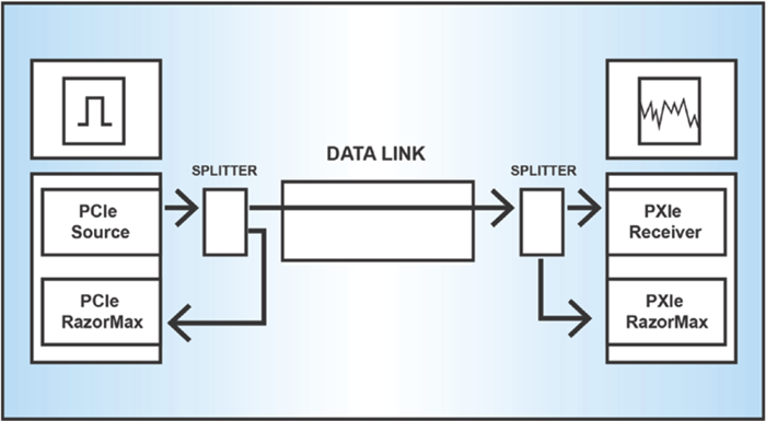
Figure 1. Two test platforms (PCle and PXle, respectively) transmit and receive the data link test signals. GaGe RazorMax high-speed data acquisition cards record the data for signal integrity comparison. Image Credit: Vitrek, LLC
The Test
The test setup uses two different PC platforms to transmit and receive the data, each using a separate protocol: PCI Express (PCIe) and PXI Express (PXIe).
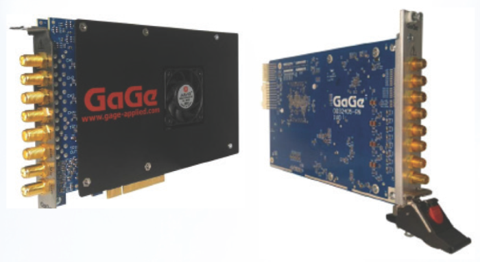
Figure 2. The GaGe RazorMax data acquisition system is offered on both PCle and PXIe platforms. Image Credit: Vitrek, LLC
To collect input and output link signals for its link characterization system, the company used two GaGe 16-bit digitizers: the RazorMax PCIe CSE 161G2 and the PXIe CSX161G2 (Figure 2). The RazorMax provides the requisite 1 GS/Second sampling rate as well as 16-bit vertical resolution, which exceeds the 14-bit requirement.
The two RazorMax models share the same GaGe digitizer hardware and just differ in their platforms (PCle and PXIe).
As a result, the input and output signals (Fig. 3a and 3b) used by the test platform software are derived from functionally identical RazorMax devices, which is the best technique to detect minor signal variations caused solely by transmission degradation.
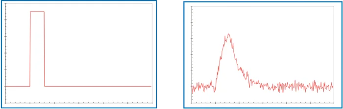
Figure 3. A GaGe PCle digitizer captures the input signal (a) being sent to the data link while a GaGe PXle digitizer captures the output signal (b). The signals are then compared utilizing analysis software. Image Credit: Vitrek, LLC

This information has been sourced, reviewed and adapted from materials provided by Vitrek, LLC.
For more information on this source, please visit Vitrek, LLC.