In this interview, industry expert Jason Chonko shares practical strategies for overcoming common challenges in high-resistance and low-signal electrical measurements by addressing noise, grounding, parasitic effects, and instrument limitations.
What are the typical challenges engineers face when measuring high resistances and low signals?
Measuring high resistances and small signals, like nanoamps of current or microvolt-level voltages, comes with a unique set of challenges. You're fighting against environmental noise, parasitic effects from your test setup, and even the limitations of your measurement equipment. High-resistance devices are especially sensitive to leakage, cable capacitance, and offsets, so understanding the fundamentals, such as grounding, signal level, and impedance, is crucial.
Why is maximizing the signal-to-noise ratio so important in high-resistance measurements?
Signal-to-noise ratio is important because noise is something you can't entirely eliminate; it’s baked into your environment. But your signal is within your control. Keeping in mind that Ohm’s Law governs resistance, the voltage drop across a resistor is proportional to the current through the resistor times the resistance in ohms, which is the elegant equation of V = IR. If we rearrange it by solving for current (I), we get I = V/R. Here, the unknown is the current. This is what we measure if we are sourcing voltage (V). So, if we source 100 mV (100E-3 V) across 1 GΩ for 1E+9 Ω, we would expect a current of 100E-12 A, equal to 100 pA. That is a very small current and can be difficult to measure, even in very electrically quiet environments. If we can bump that voltage up to 10 V, then we would measure 10 nA. This is easier to measure than 100 pA because the amplitude of the signal we want to measure is 100 times greater. The signal is even larger than the noise.
The point is, putting as much signal as you can into the device under test will make measurements easier. Remember that higher signal levels may have unintended consequences, including self-heating of the device, masking of underlying effects, device damage, and electrical safety issues. Simply increasing the amplitude does have limits.
How does cable capacitance impact high-resistance measurements?
When working at high resistances, it becomes a significant factor. Caple capacitance increases the time to charge the cable, which can lead to additional settling time to make accurate measurements and may cause instability when using auto-ranging for the measurement. This gets worse the higher the device resistance and the longer the cables.
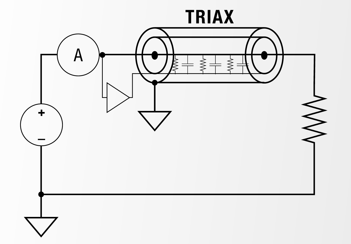
Image Credit: Lake Shore Cryotronics Inc.
When should you avoid using auto-ranging?
Auto-ranging is helpful at the beginning to get a sense of your signal levels, but it can introduce instability, especially when there’s parasitic capacitance in the system. I recommend switching to fixed ranges as soon as possible. Use the lowest fixed range that still fits your signal; it reduces noise, improves stability, and avoids discontinuities caused by range changes.
What role does grounding play in low-level measurements?
Grounding is one of the most overlooked but critical aspects. You want to tie measurement ground and earth ground together in one place only — no multiple ground points. In the recent webinar I did with AZO, I showed that disconnecting the measurement ground caused the system to float, massively increasing AC noise. Reconnecting it stabilized the reading. Knowing where the grounds are is especially important when working with systems that have more than one electrical connection, such as cryostats, probe stations, and dilution refrigerators.
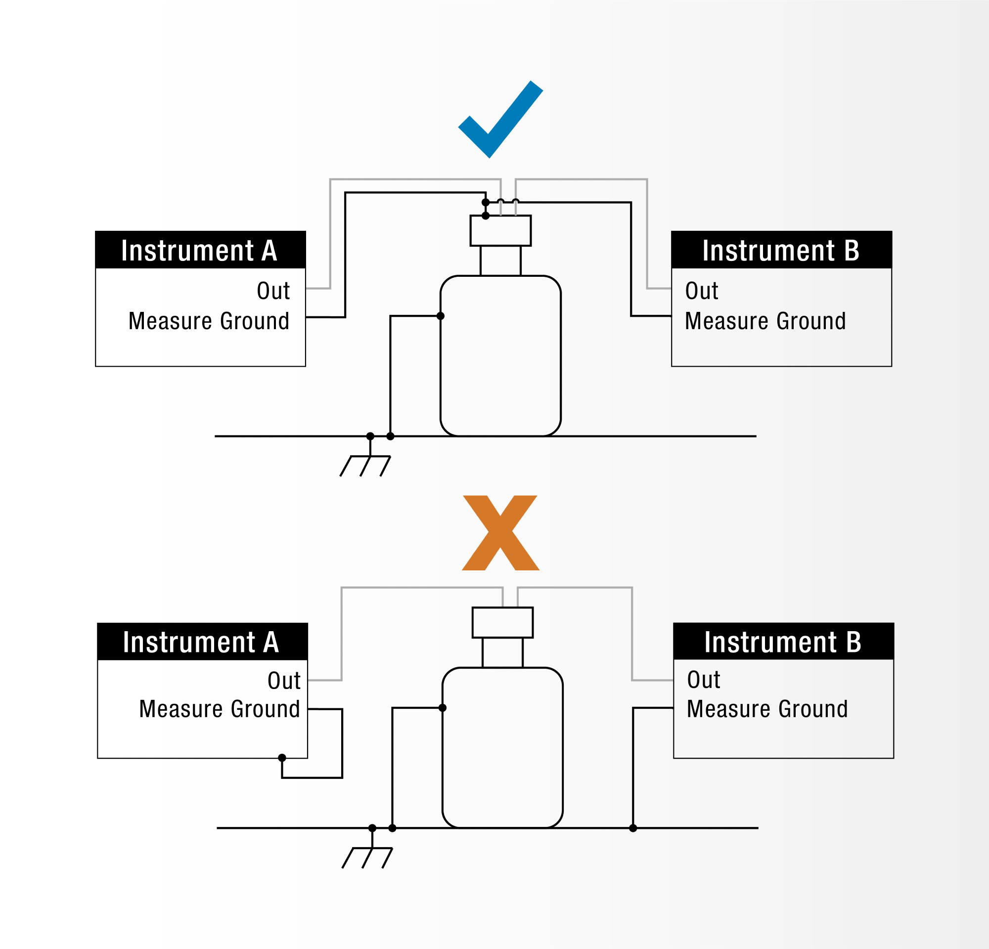
Image Credit: Lake Shore Cryotronics Inc.
Can’t I use a handheld digital multimeter or oscilloscope for high-resistance testing?
Yes, but it comes down to the input impedance of the measurement instrument. Digital multimeters (DMMs) and oscilloscope probes typically have 10-MΩ input impedance. If your device under test is 1 GΩ, you're creating a 100:1 voltage divider. This means a significant portion of the current will go through the meter instead of the device under test. I demonstrated this in the webinar by connecting the DMM, and the measured current was boosted from 10 nA to 1 µA. For high-resistance work, you need an instrument with ultra-high input impedance, like the SMU-10 in Lake Shore’s M81-SSM system, which is over 10 TΩ.
How do you deal with offset errors in the measurement system?
Offsets come from multiple sources. These can be thermal effects between dissimilar metals, like in thermocouples, as well as the circuitry inside your instruments. These offsets are typically unidirectional, so one effective approach is to alternate polarity: take a measurement with a positive source value, then take a measurement with a negative source value, and then average the two. An alternative is also an AC technique, which automatically switches polarities. The M81-SSM is unique in that it supports both DC and AC source and measure operations.
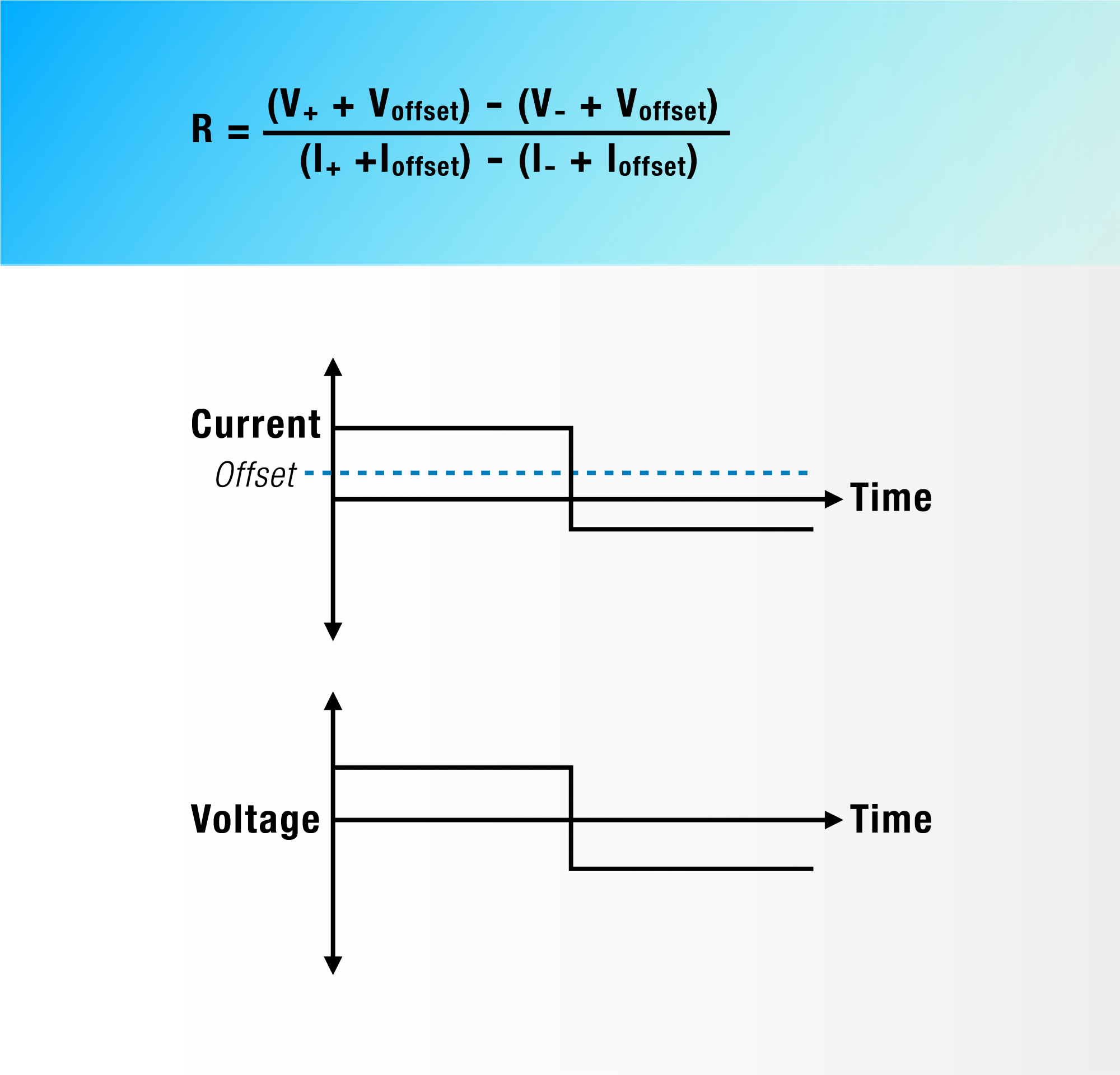
Image Credit: Lake Shore Cryotronics Inc.
What best practices do you recommend for sourcing voltage in high-resistance applications?
I recommend ramping the voltage rather than applying it in one big step. So instead of jumping from 0 to 10 V, step through in 1-V increments. That reduces the inrush current caused by parasitic capacitance, which can otherwise distort the measurement. It’s a simple trick that makes a big difference in precision, especially in sensitive systems with long cabling.
How can engineers minimize parasitic capacitance and leakage?
Parasitic capacitance mostly comes from your cables. The longer or more complex the run, the more capacitance you introduce. Use the shortest and lowest-capacitance cables possible. A twisted pair is better than a single lead; a coax cable is better than a twisted pair; and a triax cable with a driven guard is best. Guarding shields your signal line with a conductor held at the same voltage, which helps reduce both capacitance and external noise. And always use grounded enclosures like a Faraday cage to block interference.
What’s your advice to engineers working with high-impedance or low-signal devices?
My advice is to be deliberate with every part of your setup. Signal levels, grounding, cabling, and instrumentation all matter. Don’t rely on default settings or assumptions. Understand your instrument's limitations, use guarding wherever possible, and remember that good measurements come from good setups. High-resistance and low-signal testing is tricky, but with the right techniques, it becomes much more manageable. Also, talking to equipment suppliers who have a history of helping others with these types of measurements can also be very helpful.
About Jason Chonko 
Jason Chonko is a Senior Pre-Sales Application Engineer at Lake Shore Cryotronics with over 25 years of experience in test and measurement. He has a B.Sc. in Physics from Kent State University and specializes in electrical device characterization, helping customers to solve complex challenges through technical analysis, application insight, and cross-functional collaboration.

This information has been sourced, reviewed, and adapted from materials provided by Lake Shore Cryotronics Inc.
For more information on this source, please visit Lake Shore Cryotronics Inc.
Disclaimer: The views expressed here are those of the interviewee and do not necessarily represent the views of AZoM.com Limited (T/A) AZoNetwork, the owner and operator of this website. This disclaimer forms part of the Terms and Conditions of use of this website.