This article explains how to install the NASA-designed water-cooled end caps on your process tube.
The water-cooled tube seal should be secured to the top of the ceramic process tube. When using the furnace, water must flow at a reasonable rate to keep the O-rings cool: one slpm per end cap.
- Separate the seal components. (See Diagram).
- Slide each seal element onto the furnace tube in the specified sequence and position. The Top End Seal and Bottom End Seal are comparable. The Top End Seal features four tapped holes and an O-Ring groove, but the Bottom End Seal does not.
- Position the End Seals and Water Jacket according to the diagram.
- Apply silicone-based lubricant to the O-rings before sliding them onto the furnace tube.
- Set the Top End Seal so that the furnace tube is recessed approximately a quarter of an inch from the O-Ring grooved face.
- Secure the Tube O-Ring against the Top End Seal. Position the Water Jacket against the Tube O-Ring.
- Use four Seal Bolts to secure the Top End Seal to the Water Jacket. Tighten the bolts using a torque pattern, ensuring a uniform spacing between the Top End Seal and the Water Jacket. Adjust the Top End Seal position to maintain the quarter-inch recess to the process tube lip.
- Secure the rest of the Tube O-Ring against the rear fillet of the Water Jacket. Position the Bottom End Seal against the Tube O-Ring. To connect the Bottom End Seal to the Water Jacket, use four Seal Bolts. Tighten the bolts using a torque pattern, keeping a uniform spacing between the Bottom End Seal and the Water Jacket. Adjust the Top End Seal position to maintain the quarter-inch process tube recess while tightening.
- Secure the top and bottom end seals to the water jacket, forcing the tube O-rings against the ceramic tube.
- Using O-Ring Lube, insert the End Plate O-Ring into the Top End Seal and secure with four Seal Bolts.
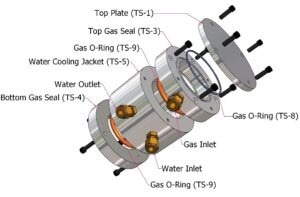
Water Cooled End Cap. Image Credit: Deltech, Inc
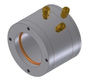
Water Cooled End Cap exterior view. Image Credit: Deltech, Inc
The Water Jacket features two quarter-inch pipe openings for connecting a water coolant intake and exit. The Top End Seal features a quarter-inch Gas Port for input or exhaust gas.

This information has been sourced, reviewed and adapted from materials provided by Deltech, Inc.
For more information on this source, please visit Deltech, Inc.