Sponsored by MKS OphirReviewed by Olivia FrostJul 23 2026
The 19th-century British scientist and engineer William Thomson, 1st Baron Kelvin, was the first to state, "If you cannot measure it, you cannot improve it." When applying this principle to improve laser-based processes, several parameters must be evaluated.
Image Credit: Andrei Armiagov/Shutterstock.com
Given the ever-increasing power of laser systems in material processing, the requirements for measuring systems are more demanding than ever. What technology is available for measuring high-powered lasers? How frequently should they be measured? What metrics should be tracked? What should happen with this data after it is collected?
As lasers are developed, producers take measurements to determine how changes in design affect performance. This data is (or should be) referenced multiple times over the laser's lifetime.
When a laser is ready to be employed for its intended purpose, the manner in which the laser light is delivered to the material being treated is often quantified in terms of power density.
Laser power and beam size can fluctuate over time for a variety of reasons, most of which stem from the second law of thermodynamics. When either the laser power or the beam size changes, the new power density influences how the laser light interacts with the material being treated (see Figure 1).
When the power density changes, the laser system no longer processes the material as intended. Once the laser system is ready for use, there are five points in the system's lifespan when gathering and using laser performance measurement data are crucial to the process's desired output.
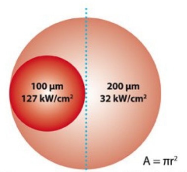
Figure 1. Relationship between power density and focus spot size. A laser beam with half of the focus spot size results in a four times higher power density. Image Credit: MKS Ophir
Lifecycle – Step 1: Application Development
The process of developing a laser application can be time-consuming and complex. Many laser settings may be adjusted to influence how the laser light interacts with material. It all boils down to the amount of laser light used and the size of the beam at the processing point.
Measuring requirements include focal spot size, spot size location, beam profile, and beam caustic, to mention a few. When considering pulsed laser applications, it is also critical to determine, by measurement, the shape and length of each pulse, since these characteristics will influence the result of the procedure.
The measure of laser performance at this point of the laser's life cycle is critical because the exact execution of the major performance criteria determines the productivity of its laser system.
This data will serve as a baseline against which future performance may be compared in the event that the end user's laser loses efficiency over time.
Lifecycle – Step 2: Laser Source Integration
The laser application is often developed in a lab environment using an efficient, optimized laser system. Once the application is completed, the settings are sent to another identical or comparable laser, which is then incorporated into the end user's system.
Although they are of the same make and model, these two lasers are not the same, as they are built from separate sets of components. The only method to handle these factors is to compare the measurements of the two systems to guarantee that the output power, beam size, and beam shape are consistent.
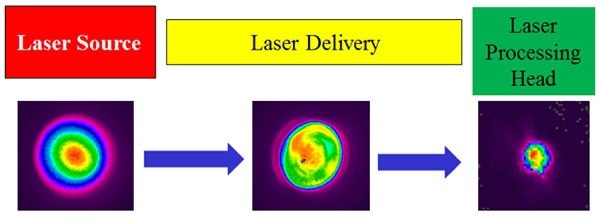
Figure 2. Different beam profiles taken at different places on the laser system beam path illustrates how the laser can change as it travels through the system. Image Credit: MKS Ophir
Lifecycle – Step 3: System Run-off, Delivery, and Movement
The transfer of the laser from the OEM or integrator to the end user can be a daunting process. The overall goal of this stage is to demonstrate to the client that the laser system is performing as intended. These laser systems are typically considered a considerable investment, meaning numerous criteria must be completed before the system is approved.
Measuring the laser and comparing the results to those obtained during the application development phase will validate the system and demonstrate to the client that the laser source and the system into which it is incorporated will function as intended. This approval procedure often occurs after the technology has been implemented at the customer's site.
Finally, when the laser system is transferred from one location to another by the end user, it is normally disassembled and reassembled. As was the case during system delivery, this can also have an impact on system integrity.
It is highly recommended that measurements be conducted on the laser system both before and after its transportation to ensure that its performance remains constant after the shift.
Lifecycle – Step 4: Periodic Measurements During Productive Use
Even if laser measurements were collected throughout the process, the system is not safe once the laser application has been developed, built, delivered, and put into production.
The second law of thermodynamics has the greatest impact on the laser throughout its longest phase of operation. At some time throughout the life of this laser system, one or more of its components will degenerate. Physical decay is unavoidable: something will go wrong with the system, whether it happens quickly or over months or years.
There are several causes of failure in laser system components. The hostile settings in which many of these systems operate are usually the root cause of the problem. Industrial lasers used for material processing, such as cutting, drilling, and welding, generate a large amount of debris throughout the process.
If not properly maintained, this process debris can cause significant damage to the laser components closest to the process, such as the protective cover glass, beam path bellows, and, in severe situations, optics or mirrors. The laser itself can also cause component deterioration issues.
Some wavelengths of light are extremely demanding on system components, necessitating continual monitoring of system efficiency. UV wavelengths are renowned for causing damage to optics and optical coatings. High peak power and power densities can result in localized heating, which can interfere with beam delivery and focusing optics.
Regardless of how the laser is used, evaluating its performance is critical at this point in its life. The deterioration of laser system components will eventually lead to a decline in system efficiency.
Laser power is anticipated to diminish over time as laser optics and mirrors increasingly absorb more laser light. Because of the thermal effects of this absorption, the laser's optics will change slightly in shape, and the focused spot will change in size or location relative to the process (known as "focus shift").
Reduced laser power, along with irregularities in laser spot size, affects power density. If laser parameters are not monitored on a regular basis, product quality will decrease without notice.
Lifecycle – Step 5: Preventative and Corrective Maintenance
Keeping the laser system working at the intended performance level requires a complete maintenance regimen, with the purpose of maintaining the laser, one of the company's most important investments.
It is advised that measurements be made before and after preventative maintenance routines to ensure that the system is once again running at peak efficiency.
Even well-maintained systems can suffer catastrophic failure of one or more of their components. Failures can be caused by defective components, poorly mounted components, inappropriate laser system functioning, and other factors. The total failure of this sophisticated system may or may not be due to a laser issue.
If the cause of the failure is unknown, measuring the laser (if it can be operated) is critical to the debugging procedure. However, if the reason of the failure is known to be an issue with the laser source, measuring the laser may typically disclose the problem very quickly.
Measurement Options
Depending on the specific applications and parts being produced, not every user is required to measure the entire range of laser parameters.
In some material processing applications, measuring laser power or energy on a regular basis may suffice for an end user. These readings may be taken using Ophir standard or OEM sensors via a computer interface or a power meter, such as the Ophir Centauri.
Ophir created the HELIOS measuring system for automated production lines. This laser power meter can detect laser outputs up to 12 kW within a few seconds and requires no cooling.
It is suitable for use in demanding manufacturing situations due to its small, durable housing and automatic shutter. Helios has Profinet or RS232 ports and may thus connect directly to any industrial network.
Users must be aware of a key limitation: a power meter is similar to the clock on a racetrack. It shows how quickly someone ran, but it does not explain why their speed changed. The same is true for laser beams; various criteria other than power or energy come into play, such as power distribution, power density, or focal shift.
Beam profiling is necessary to determine these characteristics. Camera-based solutions produce measurements by combining ordinary CCD or CMOS cameras with optical components and strong software.
Ophir has just released the LBS-300-HP-NIR attenuator, a novel beam splitter that enables the measurement of focused or collimated laser beam profiles in the NIR range (approx. 1064 nm) with a power density of up to 15 MW/cm2. However, there remains one remaining concern with high-power laser measurement: repeatability.
Repeatability of Measurements
As previously stated, there are many ways to measure laser beam parameters, depending on the application and kind of laser employed. Looking at the five stages when laser measurement is critical in the lifespan of a laser in material processing, it is clear that measurement reliability and repeatability are critical components of the process.
This is becoming progressively more advanced as laser power increases in material processing. Ophir has handled the challenge and developed a non-contact measuring method based on Rayleigh scattering.
The BeamWatch laser beam profilers employ technology that allows them to measure high-power beams without touching them. This offers four significant advantages.
Because of its non-contact nature, this approach has no realistic upper power limit for measuring lasers. Rayleigh scatter is proportional to the inverse square of its wavelength; therefore, while scatter may be measured from 1030–1080 nm sources, visible and UV sources offer a much larger signal.
There are no moving parts and no direct interaction with the laser beam, simplifying preventive maintenance, and beam attenuation optics do not wear out. The simplicity of the measurement setup improves data integrity and the comparability of data collected by different people at different times or locations throughout the laser's life cycle.
Because the critical beam characteristics are monitored in real time, regular measurements are possible, even in production scenarios. This resulted in the creation of another version of the Ophir BeamWatch system: BeamWatch Integrated, which was designed to satisfy the demands of automated manufacturing processes.
In addition to contactless measurement, BeamWatch Integrated is compatible with industrial networks and automated manufacturing processes. The system has an efficient architecture, a built-in power meter, and many interfaces for directly transferring measurement data to production networks.
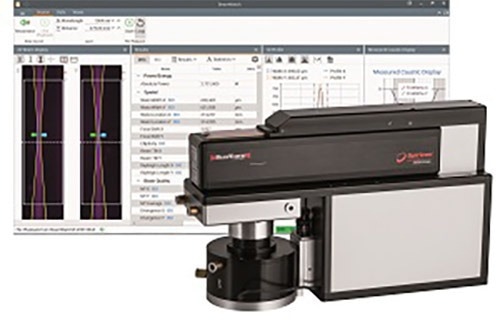
Figure 3. BeamWatch Integrated delivers key beam characters in real-time. Image Credit: MKS Ophir
Conclusion
The importance of measuring laser beams in materials processing is unquestionable: it is critical to assess power, energy, and/or beam profile along the value chain, from the laser source manufacturer to the end user of the laser system. Ophir provides a variety of solutions for ensuring laser quality throughout the laser's lifespan.
Acknowledgments
Produced using materials originally authored by Kevin Kirkham and Christian Dini from Ophir.

This information has been sourced, reviewed and adapted from materials provided by MKS Ophir.
For more information on this source, please visit MKS Ophir.