Sponsored by MKS NewportReviewed by Olivia FrostAug 27 2026
A translation stage constrains motion to a specific direction: for example, a linear stage's desired motion is along an ideal straight line. Any motion in constrained directions will result in a departure from the ideal trajectory and/or position.
There are multiple contributors to deviations, including load forces and imperfections in machining and materials.
Ultimately, high-performance motion systems are complex, and missing a seemingly minor issue, whether in design or application, can lead to unfavorable outcomes. Thus, a product's intended use, as well as the numerous performance measures, must be thoroughly assessed.
Coordinate System and Sign Convention
Any positioning stage is considered to have six degrees of freedom: three linear along the x, y, and z axes, and three rotational around those same axes (Figure 1). All motions described here use the right-hand coordinate system convention.
The +Z axis (thumb) is the intersection of the +X and +Y axes (pointer and middle fingers). Also, if the right hand's thumb points in the positive direction of an axis, the fingers will wrap around it in the positive rotation direction.
All movements consist of translations along and/or rotations around the coordinate axes. In general, the X and Y axes are horizontal (the first or bottom stage's direction of travel is aligned with the X axis), while the Z axis is vertical.
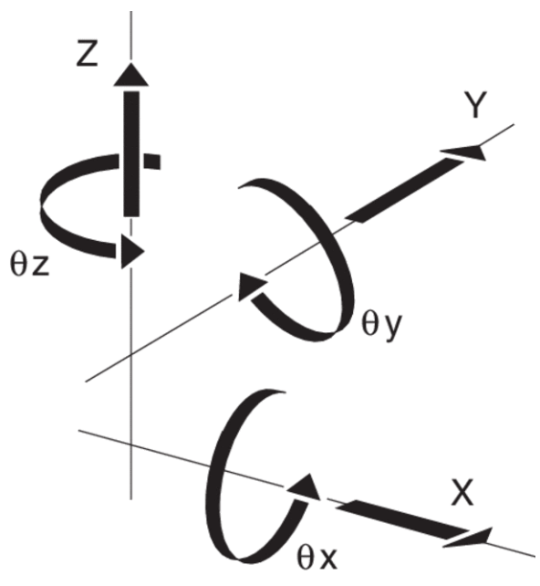
Figure 1. Right-hand coordinate system showing six degrees of freedom. Image Credit: MKS Newport
Runout of a Linear Stage
A linear stage's runout is the linear (rather than angular) fraction of off-axis error. It is a deviation from the desired, ideal straight-line motion made up of two orthogonal components. In the ISO-230 and ASME B5.57 standards, runout is referred to as straightness or lack thereof.
However, in the motion industry, the terms flatness and straightness are commonly used; Figure 2 shows a visual representation of the two, demonstrating perfect straight-line motion confined to the x-axis. Flatness deviation refers to displacement along the z-axis, while straightness deviation refers to displacement along the y-axis.
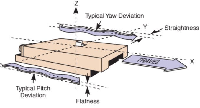
Figure 2. Off-axis deviations in a linear stage. Image Credit: MKS Newport
Tilt of a Linear Stage
The tilt of a linear stage is the angular divergence between ideal straight-line motion and actual observed motion. Tilt includes three orthogonal components known as pitch, roll, and yaw (Figure 3), and may be the result of a complex relationship between these three components.
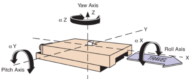
Figure 3. Roll, pitch, and yaw are defined with respect to the direction of travel. Image Credit: MKS Newport
Cross-Coupling
In multi-axial systems, cross-coupling refers to a change in one axis caused by input to another.
Abbe Error
The Abbe error is the linear off-axis error caused by the amplification of tilt by an Abbe offset moment arm (Figure 4). This type of error becomes more problematic when the point of measurement is located a significant distance from the axis of motion. This inaccuracy will be around 0.02 micrometers per 20 mm of offset per microradian.
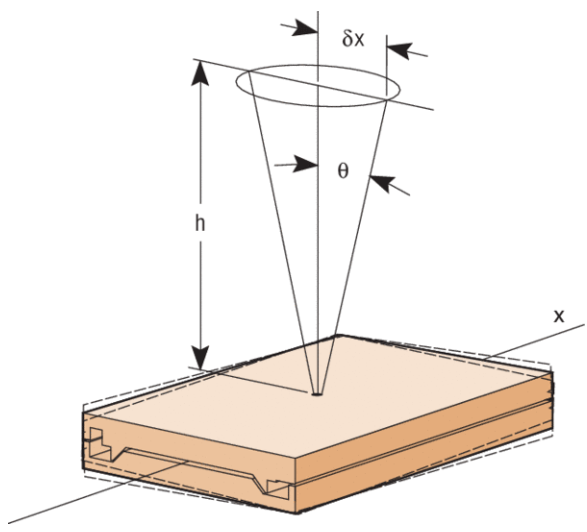
Figure 4. Abbe error due to measurement at an offset point. Note the stage tilt. Image Credit: MKS Newport
Eccentricity and Wobble of a Rotary Stage
Eccentricity is defined as the radial (perpendicular to the axis of rotation) departure of the center of rotation from its mean position as a stage spins once (Figure 5). It is also known as radial runout.
A perfectly centered stage with properly aligned bearings would have no eccentricity. Wobble is a one-revolution nutation of the axis of rotation relative to the ideal axis (Figure 5).
It is most clearly identified as a cyclic tilting of a stage's rotating surface or table top, which can result in Abbe error. It is typically caused by imperfect bearings, similar to eccentricity.
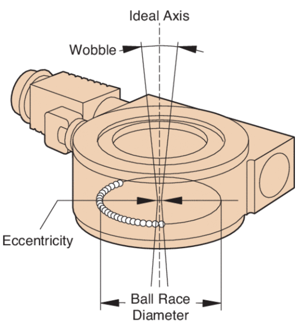
Figure 5. Off-axis deviations in a rotary stage. Image Credit: MKS Newport
Cosine Error
Cosine error is caused by a misalignment between the measurement and motion axes. This inaccuracy depends on the angle between the measurement axis and the axis of motion (Figure 6). It is eliminated when the motion and measurement axes are parallel.
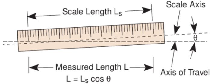
Figure 6. Cosine error due to misalignment of the measuring scale with the axis of motion. Image Credit: MKS Newport
Play
The phrase "play" refers to unrestrained movement caused by loose mechanical parts. Play contributes to backlash.
Friction
Friction is defined as the resistance to movement between two surfaces in contact. Friction-causing elements can include drag, sliding friction, depleted lubrication, system wear, and lubricant viscosity.
Stiction
Stiction is the static friction that must be overcome before a body at rest may move. Because static friction is often greater than moving friction, the force necessary to impart motion exceeds the force required to keep the body moving.
As a result, when a force is initially applied, the body begins to move with a "jump," causing position and/or velocity overshoot.
When designing a stage, one key aim is to achieve static friction as close to moving friction as possible to reduce the effect of stiction. One role of motion control electronics is to develop algorithms that mitigate the impact of stiction by immediately correcting the movement profile.
Position Stability
Position stability refers to the capacity to maintain a position within a specific range throughout time. Drift is another term for a deviation from a stable location. Wear and tear, vibration, lubricant migration, and temperature fluctuations all play a role.
Load Capacity
Load capacity is the maximum permitted force that can be delivered to a stage in a certain direction while still matching stage standards. This maximum force comprises both static (mass * gravity) and dynamic forces (mass * acceleration).
Dynamic forces must incorporate all external forces acting on the stage, such as vibrations. The acceleration a stage can provide to a mass is limited by the accelerating force it can generate without exceeding its load capacity.
Torque is the rotary stage equivalent of force. When cantilevered loads are accelerated, rotational torques on linear stages can play an important role. Unless otherwise noted, catalog load capabilities are for a centered normal load (Figure 7).
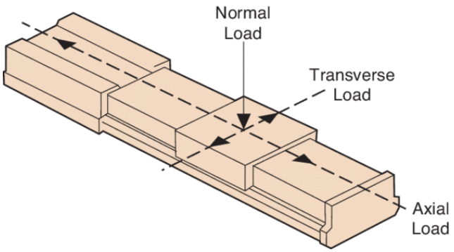
Figure 7. Capacity specifications refer to loads that are centered and perpendicular. Image Credit: MKS Newport
Centered Normal Load Capacity
This is the maximum load that may be applied to a linear stage, with the load center of mass in the center of the carriage, perpendicular to the axis of motion and the carriage surface (Figure 7). For rotary stages, it refers to the maximum load along the rotation axis. Furthermore, the rotational moment of inertia must be within limitations for rotary stages.
Transverse Load Capacity
Also known as side load capacity, this is the greatest load that may be applied perpendicular to the axis of motion and along the carriage surface (Figure 7). This is usually smaller than the standard load capacity.
Axial Load Capacity
The maximum load in the direction of the drivetrain is referred to as the axial load capacity (Figure 7). For vertically mounted linear stages, the axial load capacity typically limits the required vertical load capacity. When mounting a stage vertically, cantilevered loading must be considered.

This information has been sourced, reviewed, and adapted from materials provided by MKS Newport.
For more information on this source, please visit MKS Newport.