IRSX cameras are designed to send results to the control layer, rather than raw images. Such results include trends, sent to SCADA, MES, or the cloud via OPC UA or MQTT; ROI temperatures and alerts sent to PLCs over Modbus TCP or PROFINET; and radiometric frames sent to vision software over GigE Vision.
This article outlines the IRSX-I640 and IRSX-I336, which are used for ongoing preventive maintenance monitoring. Examples of register maps, subjects, and addresses are displayed, which should be compared with IRSX firmware documentation.
Why Integrate?
Before they result in obvious damage, a lot of mechanical and electrical issues can elevate the system's temperature.1 Periodic thermography is converted into continuous monitoring of motors, bearings, switchgear, connections, pumps, and transformers via a fixed camera that is hooked into the control system.
Source: Pembroke Instruments, LLC
| Workflow step |
How integration supports it |
| Establish a baseline |
Log ROI values under known load via OPC UA or MQTT |
| Inspect consistently |
Fixed mount and field of view; a PLC load signal gates measurements |
| Compare and trend |
Phase-to-phase or twin-asset ROIs compared in camera or SCADA |
| Investigate exceptions |
Alarm to the PLC; event and snapshot to the CMMS work order |
Load, airflow, viewing angle, emissivity, and reflections should be controlled, and any temperature changes should be recorded. Camera alarms are not a safety feature; rather, they provide condition monitoring.
IRSX Interfaces
No PC is required at the camera because the IRSX measures ROIs and sounds alarms on board. In addition to an I/O cable for triggers and alarm outputs, it requires 24 VDC and GigE Ethernet on rear M12 connections; DHCP is enabled from the factory (see the IRSX setup instructions).2
Source: Pembroke Instruments, LLC
| Interface |
Best use |
| Modbus TCP |
ROI values and alarm bits into any PLC or SCADA |
| PROFINET |
Cyclic data with Siemens S7-1200/1500 |
| OPC UA |
Secure data to SCADA, MES, and historians |
| MQTT |
Events and trends to brokers, IIoT, and CMMS platforms |
| REST API / HTTPS |
Configuration, backups, and snapshots |
| GigE Vision + GenICam |
Radiometric streaming to Halcon, LabVIEW, MATLAB, Cognex |
| Digital I/O |
Hardwired alarms, triggers, and load signal |
| Lua scripting |
In-camera ΔT, debouncing, and load gating |
The IRSX protocol document does not mention EtherNet/IP; instead, Rockwell sites should utilize Modbus TCP or a gateway.
Architecture
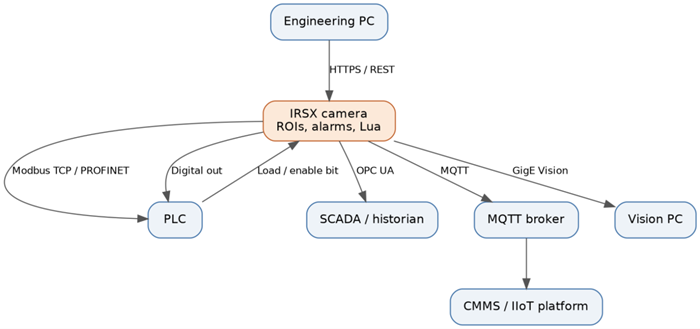
Reference integration architecture. Image Credit: Pembroke Instruments, LLC
Use a hybrid for essential assets: trends are sent to SCADA or a broker, while alarms are sent to the PLC via the fieldbus and a hardwired output.
Allow one system to regulate each alarm threshold and keep visual streaming off the control network. Since thermal issues take minutes to weeks to develop, poll every second for PLCs and every 10 to 60 seconds for trends.
Protocol Setup
Modbus TCP
- Enable Modbus TCP (port 502) and set a static IP.
- Map alarm bits and ROI values to registers.
- Set up the PLC client (such as Siemens MB_CLIENT, Micro800 MSG_MODBUS, or a ControlLogix gateway) and poll FC03/FC04 every 0.5–1 second.
- Compare values with the live readout via the web interface.
The majority of problems are caused by 0- vs 1-based addressing and float word order.
PROFINET
- Open the TIA Portal and import the IRSX GSDML file.
- Add the device, give it a name, and use DCP to assign it.
- Add the ROI and alarm modules; a 32–128 ms update time is sufficient.
- Download and verify that the device appears green in the diagnostics.
OPC UA
Use Basic256Sha256 with Sign & Encrypt to establish a connection to opc.tcp://<camera-ip>:4840. Give historians a read-only account and exchange certificates. Subscribe instead of poll, with a deadband of 0.2–0.5 °C and a sample interval of one second.
MQTT
Use a distinct client ID to establish a TLS connection on port 8883. Choose a topic like plant/area/asset/irsx-01/roi/3. Set a retained status topic with a Last Will, publish values every 10–60 seconds, and set alarms for changes at QoS 1.
REST, GigE Vision, Digital I/O, and Lua
- REST: Attach alert snapshots to work orders, push ROI updates, and backup setups. Use HTTPS only.
- GigE Vision: GVCP uses UDP 3956, while GigE Vision requires a dedicated NIC, jumbo frames, and the 16-bit radiometric format.
- Digital I/O: Wire the load signal as an input and maintain the critical alarm output normally activated so that power loss appears as a defect. Check voltage ratings before proceeding.
- Lua: Compute phase ΔT and rise over ambient, apply 30–60 s, and gate alerts on load.
ROIs and Alarm Thresholds
On the component itself, draw ROIs; these will ideally be 10 by 10 pixels, though they can be as small as 3 by 3.3
Before turning on alarms, pair each with a reference ROI, adjust emissivity for each ROI, and allow the camera to warm up. T_max, T_avg, dT_ref, dT_amb, Alarm_state, and a Valid flag are the identical tags that should be published on all protocols.
Use gate alarms on at least 40% load and the NETA MTS ΔT requirement for electrical assets:4
Source: Pembroke Instruments, LLC
| NETA priority |
ΔT vs similar component |
ΔT vs ambient |
Suggested alarm |
| 1 |
>15 °C |
>40 °C |
Critical: output, fieldbus, work order |
| 2 |
– |
21–40 °C |
Warning |
| 3 |
4–15 °C |
11–20 °C |
Warning |
| 4 |
1–3 °C |
1–10 °C |
Advisory: trend only |
Set baseline restrictions for mechanical assets (e.g., +10 °C, or a climb faster than 2 °C/hour). Add a delay of 30 to 60 seconds, add 2 to 3 °C hysteresis, and latch critical alarms.
Network and Security
Install cameras on an OT VLAN using NTP and static addresses. TCP 502 (Modbus), 4840 (OPC UA), 8883 (MQTT), 443 (HTTPS), and UDP 3956 (GigE Vision) are the only ports that should be allowed.
Modify default passwords, designate administrator, integrator, and worker levels for roles, disable unnecessary protocols, and create backups of configurations and scripts.
When operating near switchgear, adhere to arc-flash regulations and install air purge or heat shields as necessary.
Checklist for Commissioning
- The camera is in focus at a working distance, and the pixels on target are confirmed.
- Static IP is configured, and power and I/O polarity have been checked.
- ROIs, emissivity, and reference ROIs are configured; readings are compared to a portable.
- Fieldbus values are successfully decoded.
- Every alarm level is forced and linked to the PLC, HMI, and CMMS.
- Power and network are pulled, and the valid flag and fault output are verified.
- After two to four weeks, the baseline is recorded, and the thresholds are evaluated.
Acknowledgments
Produced using materials originally authored by Leslie M. Tack, PhD, Chief Technical Officer, Pembroke Instruments.
References and Further Reading
- Pembroke Instruments | Pembroke Instruments. (2026). Thermal imaging for industrial preventive maintenance. Available at: https://pembrokeinstruments.com/applications/thermal-imaging-applications/thermal-imaging-for-industrial-preventive-maintenance/.
- Pembroke Instruments | Pembroke Instruments. (2026). How to set up an IRSX thermal camera. Available at: https://pembrokeinstruments.com/resources/thermal-imaging-scientific-guide-to-long-wave-infrared-lwir/how-to-setup-an-irsx-thermal-camera/.
- Pembroke Instruments | Pembroke Instruments. (2026). IRSX thermal imaging calculator. Available at: https://pembrokeinstruments.com/irsx-calculator/.
- Janki Devi Memorial College (2024) Thermography Report 2024–25. Available at: https://www.jdm.du.ac.in/Audit-Reports/2024-25/Thermography-Report-2024-25.pdf

This information has been sourced, reviewed and adapted from materials provided by Pembroke Instruments, LLC.
For more information on this source, please visit Pembroke Instruments, LLC.