
Background
LSM has provided analytical services to many industries since the sixties, including from its purpose built state of the art facilities since 1990. LSM is accredited to UKAS (laboratory 1091) for most of its methods. As part of the LSM group it has served the accurate and fast turnaround requirements of its wide range of customers for many years. During this time LSM has also developed its capabilities in terms of the range of analysis techniques, methods and its people. By working with its customers and being involved in the early stages of the development of emerging industries, LSM is now able to offer a wide range of analytical services.
X-Ray Diffraction (XRD) and X-Ray Fluorescence (XRF)
History and Use of X-Rays for Analysis
X-rays are electromagnetic radiations having wavelengths roughly within the range from 0.05 to 100 Angstroms. They were discovered in 1895 by Rontgen. Their similarities to light led to the tests of established wave optics: polarisation, diffraction, reflection and refraction. With limited experimental facilities Rontgen could find no evidence of these, and so called them “x” (unknown) rays.
The essential wave nature of x-rays was established in 1912 by Laue, Friedrich and Knipping. They showed that x-rays can be diffracted by a crystal, acting as a 3-D diffraction grating.
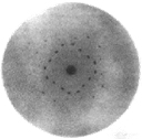
Figure 1. X-ray diffraction pattern from a crystal.
Scattering experiments by Barkla and Sadler in 1908 showed x-rays to contain components characteristic of the target material. In 1913 Bragg showed by diffraction experiments that these radiations have sharply defined wavelengths.
Braggs Law
Braggs law describes the mechanism by which x-ray diffraction occurs and was an extremely important discovery; it formed the basis for what is now known as crystallography.
Figure 2. Schematic representation of x-ray scattering from a crystalline material.
In the same year Moseley showed the wavelengths were not only characteristic of the element the target was made of, but also they had the same sequence as the atomic numbers. This allowed atomic numbers to be determined unambiguously for the first time.
Soon after it was also established that secondary fluorescent x-rays were excited in any material irradiated with beams of primary x-rays. This started investigation into the possibilities of fluorescent x-ray spectroscopy as a means of qualitative and quantitative elemental analysis
X-Ray Diffraction (XRD)
LSM has developed a suite of programmes internally to allow a range of determinations to be made including:
• Phase identification of crystalline materials
• Phase quantification, including crystalline silica
• Glass content of GGBS
• Customer specific quality control methods
LSM’s analysis development team also develops new methods to meet customer requirements.
X-Ray Fluorescence (XRF) Sample Preparation
As with any analytical method, sample preparation is crucial and LSM was one of the early pioneers of the borate glass bead technique, developing methodology for analysis of refractory and rare earth oxide mixtures as well as a range of ferroalloys, steels and hard metal carbide powders. This is a valuable way to eliminate errors with materials, which exhibit varying composition, or are difficult to present in other forms.
X-Ray Fluorescence spectrometry (XRF)
XRF provides determination of major and trace elements in solids. There are 2 types of XRF spectrometers:
• Wavelength dispersive (WDX or WDS); superior resolution and detection limits
• Energy dispersive (EDX or EDS); smaller, often portable
Elements are measured simultaneously using a number of pre-assembled fixed channels placed around the sample. Each is effectively a self contained spectrometer, with a crystal and detector tuned to receive a specific wavelength.
LSM also provides an excellent semi-quantative package, which covers all the elements from fluorine to uranium measurable by XRF in one analysis. Useful results can be obtained from even small samples. By combining a semi-quantative analysis with XRD, a cost effective investigative tool is available for deposits, corrosion, contamination or other unknowns.
Atomic Absorption (AA)
An atom consists of a core containing neutrons and protons. It also has a surrounding number of electrons, which are bound to the core at different energy levels. When an electron makes a transition from a particular energy level of an atom to a lower energy level, a photon of energy is released, which is equivalent in energy to the reduced level for the electron. The photon forms an atomic spectral line.
Figure 3. Schematic of energy drop when an electron moves from to a lower energy level.
The frequency (v) at which the spectral line occurs is related to the energy (E) by Planck`s law; E = hv, where h is Planck’s constant. The atomic radiation produced can be characterised by both emission and an absorption coefficients.
Inductively Coupled Plasma – Optical Emission Spectrometry (ICP – OES)
When a material is heated sufficiently it will emit visible light in a discrete spectrum, characteristic of the elements in the material. Each element has its unique atomic emission spectrum (both visible light and x-rays), allowing analysis via ICP-OES.
There are 3 common methods to heat a sample to produce the optical emission:
• arc/spark instruments; heat in a spark discharge
• ICP; dissolve sample in acid and “burn” the solution in an argon plasma
• Glow discharge; sputter the surface with argon, and excite the sputtered atoms
In the following the ICP and OES are briefly described. The ICP is simply the means by which the heat is generated. The ICP is essentially a high energy source (plasma) to raise the energy levels of electrons, and so induce an optical emission.
Inductively Coupled Plasma Heating
There are 3 stages in the life of a light beam; it is created it travels through space and it is destroyed. The ICP is the means used to create the light beam. It is the interaction of light with electrons, which is responsible for its creation and destruction.
In terms of the dual wave like and particle like behaviour of light, it is simplest to envisage the particle like behaviour in terms of photons. As described under atomic absorption, electrons can be raised to higher energy by absorbing photons (destroy light), or move to lower energies by giving off a photon (create light).
Figure 4. Schematic of inductively coupled plasma heating.
Optical Emission Spectroscopy
In atoms, the electrons are negatively charged and are held or bound by the positively charged protons in the nucleus of the atom. It is the specific binding energy of different elements, which determines their specific optical emissions.
Heat encourages light to be emitted over the whole energy region of visible light. The purpose of the ICP is to produce a spectrum of narrow lines, distributed in energy across the visible spectrum. Each line is characterised by the element atom, which emits the light.
Carbon, Sulphur, Nitrogen, Oxygen Analysers
Using Leco analysers gaseous elements can be analysed to trace levels in a range of materials. The equipment allows range extension for C and N in carbides and nitrides as follows:
• Carbon- converted in an oxygen atmosphere to CO2, which is then detected by infra-red.
• Sulfur - converted in an oxygen atmosphere to SO3, which is then detected by infra-red.
• Nitrogen - N2 measured by thermal conductivity.
• Oxygen - graphite crucible used to burn the sample and generate CO2, which is then detected by infra-red.
Hydrogen Analysis
The sample is heated in a crucible in a current of Helium.
The hydrogen is released/extracted into the helium gas and detected using thermal conductivity.
Boron Analysis by The Neutron Transmission Method
LSM has developed techniques for the analysis of boron by neutron transmission where dissolution methods have proven difficult.
Colorimetric and Volumetric Analysis
LSM carries out several classical wet methods of analysis.
Particle Size Analysis
• Sieve analysis - using a range of certified sieves for particle size distribution determination.
• Laser diffraction - produces a full set of data for the particle range 0.02 to 2000 microns.
Specific Surface Area
The BET nitrogen gas absorption method provides pore size distributions and pore volume parameters for mesoporous materials.
Light Microscopy
Sample preparation for light microscopy is not easy, as a highly polished flat surface is usually required for best results. All microscopes contain a lens, which bends light to allow a clearer image to be seen. In a light microscope the lens magnifies small things so that they appear larger.

Figure 5. Microstructure of a hyper-eutectic Al-Si piston alloy.
The laboratory has many years experience in metallographic sample preparation, testing and examination. In particular it carries out daily checks on the company`s range of Al based master alloys and TiBAl grain refiners.
Scanning Electron Microscopy (SEM)
The laboratory has access to the very latest generation of high resolution imaging equipment.
Figure 6. Scanning electron microscopy unit available at LSM Analytical.
In addition to high magnification imaging the SEM has analysis instrumentation known as Energy Dispersive Spectrometer (EDS), which allow analysis of an area of approximately 1um in diameter. This allows analysis of phase boundaries, surface imperfections, comparison of different areas of the sample etc. Past generations of SEM's required the sample to be electrically conducting, which required a coating of gold or carbon to be sputtered on the surface. However, if the sample is electrically insulating by applying a coating then the sample can be now be imaged in low vacuum mode.
WEEE and RoHS Directives
• WEEE: Waste Electrical and Electronic Equipment directive enforced 01/07/06.
• RoHS: Restriction of the use of certain Hazardous Substances
The European Union directives WEEE and RoHS govern the return of used electrical and electronic equipment, their re-use or their recycling. These regulations include a ban on hazardous substances including the elements lead, cadmium, chromium (VI) and mercury as well as polybrominated diphenyls and polybrominated diphenylethers (flame retardant in plastics) in the manufacture of electrical and electronic equipment.
The maximum limits are being defined by the EU’s Technical Adaptation Committee. The first proposed limits for these substances are 0.01% for cadmium and 0.1% for the other substances.
Source: LSM Analyical.
For more information on this source please visit LSM Analyical.