The paint chips obtained from vehicles involved in road accidents contain vital evidence for solving criminal cases. Paint traces can be transferred from a vehicles to other materials or surfaces like the clothes of the victim. These traces can be matched with the type of paint of the vehicle using IR analysis.
Traces of paint can be transferred from a vehicle onto other surfaces or materials, such as victims clothing, and these can be matched to the paint type of the vehicle. This is achievable since the paint chips are multi-layered materials consisting of several coats of paint.
The combinations in each layer are distinct for an individual manufacturer and the colour, model and year of a specific vehicle. Paint samples in forensic paint investigations are measured through standard Infrared Spectroscopy (IR) techniques guided by ASTM method E2937-13.
Very small paint samples, in the order of a few micrometers in size, can be measured using infrared microscopes where spectra are recorded for each layer. This article explores the application of various sampling modes and the automation features of the Spotlight™200i IR microscope system for the analysis of the automobile paint chip samples retrieved from the scene of a road accident.
Transmission, Attenuated Total Reflectance (ATR) and specular reflectance are the three main sampling techniques in infrared spectroscopy. All the three sampling techniques can be applied to IR microscopes for microsamples and standard (macro) IR accessories. The application of all these techniques to the paint chip sample, and the advantages and disadvantages associated with each of them are described here.
Reflectance
The direct reflection from the sample cross-section is a measure of the specular reflectance. There is only minimal sample preparation involved in the reflectance sampling mode because the sample is securely positioned on the IR microscope stage with the help of a small clamp device. Figure 1 shows the visible image of the sample obtained by reflectance in which multiple layers are shown.
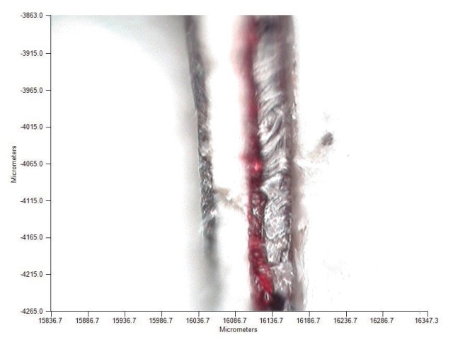
Figure 1. Visible image of cross section of a paint chip sample on IR microscope.
Though preparation of the sample and gathering spectral data is easy, the reflectance technique is not an optimal method due to the presence of distortions in the reflectance spectra caused by peak shifts and changes in refractive index. As a result the reflectance spectra cannot be compared with the reference spectra obtained from recording transmission.
The reflectance spectra obtained from the layers of this sample represent a typical reflectance spectrum from a paint sample, as shown in Figure 2. A gold mirror reference was used to record the background spectrum.
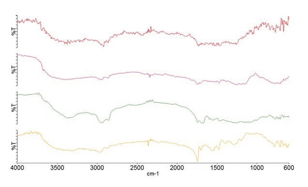
Figure 2. Specular reflectance spectra of paint layers.
Attenuated Total Reflectance (ATR)
The ATR technique is a surface reflectance technique where the IR radiation only penetrates 1-2µm into the sample. Therefore, even thick samples can be measured using this technique with minimal sample preparation by making a simple cross-sectional cut of the sample to reveal the layers.
The sample can be securely placed on the microscope using a clamp device, or even embedded in a resin block and polished. By embedding the sample, it is supported better and any distortion on the application of pressure by the ATR crystal is eliminated. Thus, the sample is preserved for repeat measurements when required. Figure 3 shows a section of the paint chip that was embedded in a resin for ATR measurements.
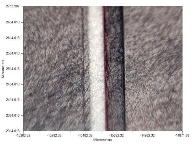
Figure 3. Visible image of a cross section of a paint chip embedded in resin for ATR measurements.
An automated drop-down ATR crystal with a tip size of 100µm is fitted on the Spotlight 200i system. This arrangement permits measurements to be taken at discrete points on the sample. Linescans or maps may also be collected from the data. An alternative method is using the ATR accessory for the IR microscope.
In this method, the crystal on the accessory is clamped to cover the entire sample, eliminating the need to move the crystal. This arrangement enables better spatial resolution and allows the measurement of thinner layers. Figure 4 shows the data of the linescan measurement that was performed with the Macro ATR accessory across the paint chip.
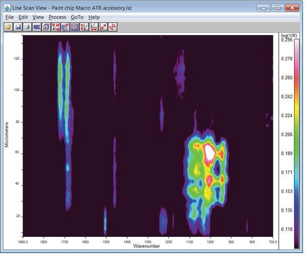
Figure 4. ATR linescan data for paint chip.
Figure 5 shows the spectra that are obtained for different layers.
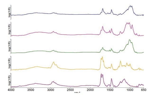
Figure 5. Spectra obtained for the different layers in the ATR experiment.
The ATR spectrum is offers more advantages over the specular reflectance spectra because it resembles an equivalent transmission spectrum. The correction processing routines in ATR aim to rectify the intensity discrepancies between ATR and transmission spectra that are wavelength-dependent. Such a correction facilitates the comparison of ATR spectra with the large library database of transmission spectra. Spectra are shown in Figure 6 comparing the ATR spectrum
with the transmission sample for the same paint layer demonstrating the equivalence of the spectra using the two techniques.
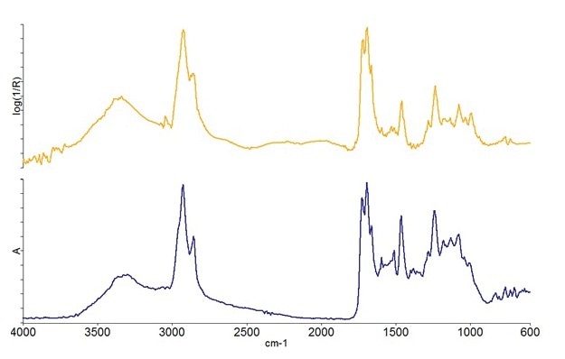
Figure 6. ATR-corrected spectrum (top) and transmission spectrum (bottom) for one of the layers in the paint chip sample.
Transmission
For IR transmission measurements the sample thickness should be 10-20µm so that occurrence of totally absorbing bands is avoided. For paint chip samples, this requires the sample to be microtomed to an acceptable thickness prior to measurement. The paint chip sample was microtomed and placed onto the surface of a potassium bromide (KBr) window, shown in Figure 7.
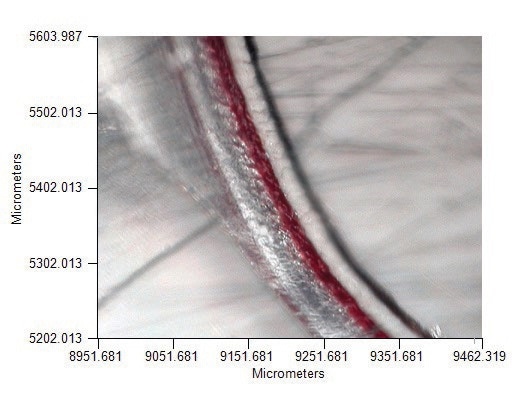
Figure 7. Microtomed paint chip sample is shown on KBr window for transmission measurement.
In order to gather the spectral information of all of the layers, a linescan was set to measure spectra at five-micrometer intervals across the entire width of the paint chip. The linescan data is shown as Figure 8.
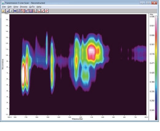
Figure 8. Transmission linescan data for paint chip sample.
It can be seen from the linescan data that different sections of the sample show different spectral features, each section representing a layer. Spectral data from each of these layers can be derived from the linescan, as shown in Figure 9.
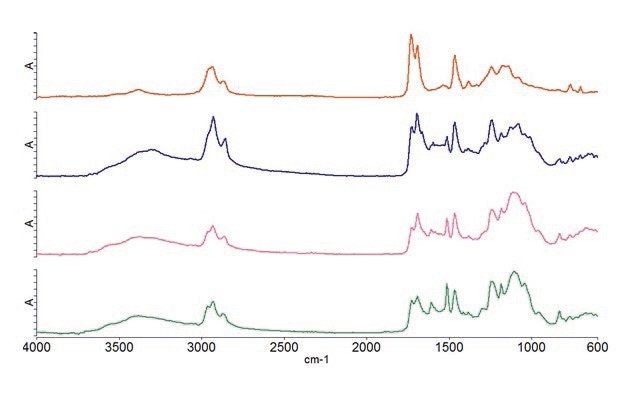
Figure 9. Shown here are transmission spectra of the layers in the paint chip.
The obtained transmission data can be compared with the data of paints and additives available in the standard libraries for identification of the layers.
Conclusion
Taking measurements from multiple layers of paint chips can be effectively achieved using IR microscopy techniques. Selection of the sampling technique depends on the sample preparation methods available, and the information needed from the spectrum. The specular reflectance method is a no-sample preparation technique that shows spectral differences between the layers. However, the obtained spectra contain distortions and a direct correlation with the transmission spectrum libraries is not possible.
ATR also offers a no-sample preparation solution if the sample is held in a clamp device on the microscope sample stage. However, the embedding method is far more advantageous. The obtained spectra in ATR can be correlated with transmission spectra and the database after the ATR correction has been implemented. By using the macro ATR accessory the spatial resolution is improved, enabling the measurement of thinner layers.
Transmission is the most preferred method for measurement of paint samples because the spectral data can be directly compared to the existing reference spectra and spectrum databases. Unlike reflectance and ATR spectra, transmission measurements do not show distortions or need any mathematical corrections. However, this measurement requires the sample to be no thicker than 15 to 20 micrometers, thus requiring some level of sample preparation of the samples to be microtomed.

This information has been sourced, reviewed and adapted from materials provided by PerkinElmer.
For more information on this source, please visit PerkinElmer.