Sponsored by QATMAug 4 2017
Invented in 1983 and patented in 1986 by C. Hull, the 3D printing technology (initally named “stereo lithography”) is a well-established production method in today's industries. Forecasts predict a growth of 774% in the global turnover during the next five years – which makes 3D printing one of the most prospering markets in the near future.
One of the numerous 3D printing techniques is additive laser powder build-up welding. This method is characterized by coating materials in powder form with the aid of laser welding. The preferred shape of the specific product is created by following trajectories which are predefined before manufacturing. The laser’s energy melts the used metal powder producing a welding bead. The final geometry is given its 3D contour by the overlapping of the welding beads according to the paths of the predefined trajectories. Optimization of the additive laser powder build-up welding focuses on economical processing with superior quality and accuracy. Focus is also on scalability: large scale on the one hand and implementing microstructures less than 100 µm on the other.1
The materials used for additive laser powder build-up welding are mainly:
- Steel
- Light metal
- Nickel super alloys
- Hard materials (carbides)
- Intermetallic materials
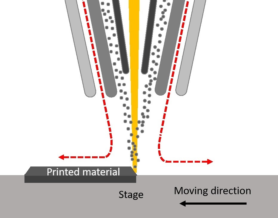
Figure 1. Process of additive laser powder build-up welding.
Materialographic Preparation Process
In the following article, the materialographic preparation process of a sample produced by additive manufacturing is demonstrated. In materialography, a sample obtained from a work piece is referred to as a specimen.
A common materialographic analysis includes the following steps:
- Sectioning (for example - with an abrasive cutter)
- Mounting, which offers a number of advantages for additional preparation
- Grinding/polishing for the preparation of the microstructure
- Examination
- Image analysis
- Hardness testing
Here, a steel sample (X6Cr17, material number: 1.4016) manufactured by additive laser powder build-up welding was analyzed. The primary step was to get a smaller sample piece (specimen) which is representative of the whole workpiece. This was accomplished by using ATM’s Brillant 210 A precision cutter with a thin CBN (cubic boron nitride) blade (wheel thickness: 0.65 mm, wheel diameter: 153 mm) as illustrated in Figure 2.
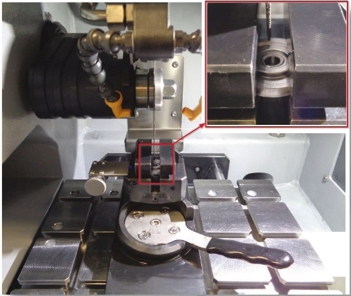
Figure 2. Brillant 210 A machine setup. Detail: clamped sample (clamping tool: vertical vice single).
The cutting was done with a pulsed direct cut (0.2 mm forwards and 0.2 mm backwards) with a rotational speed of 4500 rpm and a feed speed of 1 mm/second. After cutting, the specimen was mounted in a hot mounting material (Epo black) with an ATM Opal X-Press hot mounting press to attain a specimen which is easier to handle. Mounting was done with a pressure of 200 bar for 6 minutes at 180 °C, followed by a cooling cycle of 6 minutes. Another benefit is the high degree of parallelism of the mounted specimens of 51 µm ± 1 µm (the tolerances are based on the caliper used for height measurements of the specimens).
The mounted specimens were ground (individual force) and polished (individual force) later using a semi-automated grinding and polishing machine, ATM’s Qness 250/750/3000. The grinding process was separated into two steps. The first one was plane grinding with a silicon carbide (SiC) grinding paper with grit size P240 to eliminate all deformations caused during the cutting process. Next, grinding was performed with a SiC paper with grit size P600 to smooth the surface for following polishing steps. First, the specimen was prepolished with the hard Galaxy BETA polishing cloth and 9 µm polycrystalline diamond suspension, after that a medium-hard cloth made of silk (ATM: GAMMA) and 3 µm poly diamond suspension. The final step, called final polishing, was performed on a soft synthetic polishing cloth (ATM: OMEGA) and Eposil M. The full preparation parameters are given in Table 1.
Table 1. Grinding and polishing parameters.
| Step |
Medium |
Lubricant/ suspension |
Speed platen [rpm] |
Direction sample holder |
Single load [N] |
Time [min] |
| Grinding |
SiC P240 |
Water |
150 |
Clockwise |
30 |
1:00 |
| Grinding |
SiC P600 |
Water |
150 |
Clockwise |
30 |
1:00 |
| Polishing |
BETA |
Alcohol, diamond 9 µm (poly) |
150 |
Counterclockwise |
35 |
4:30 |
| Polishing |
GAMMA |
Alcohol, diamond 3 µm (poly) |
150 |
Counterclockwise |
35 |
4:00 |
| Polishing |
OMEGA |
Water, Eposil M |
100 |
Clockwise |
30 |
1:30 |
According to this preparation sequence, a finely polished specimen surface was acquired. Figure 3 reveals an image captured with an incident optical microscope (incident light) at a magnification of 100.
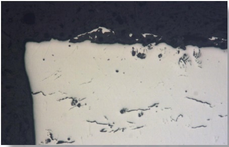
Figure 3. Image of the prepared specimen surface. Due to the polished surface the light is reflected almost equally and the microstructure is not discernible.
As the light is reflected nearly equally over the entire specimen surface, the microstructure is not discernible. Because of the nature of the human eye, a minimum difference in contrast of 10% is required to make the contrast visible on any surface. This contrasting is achieved by etching. The example used here - the etchant “V2A Beize” for pickling was used to contrast the surface by selective etching of the varying phases of the examined X6Cr17 steel. Etching was performed for 45 seconds and the microstructure is clearly visible as can be seen in Figure 4.
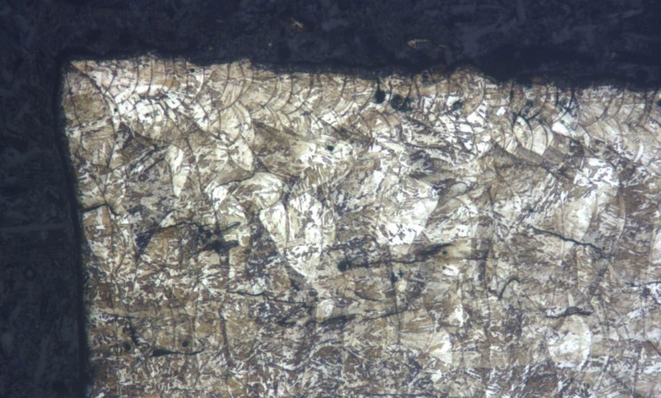
Figure 4. Etched specimen using "V2A Beize" (for 45 s). Edge section. The microstructure is clearly discernible.
The microstructure was also contrasted well in the center of the specimen surface indicating that the total prepared surface was effectively contrasted as illustrated in Figure 5.
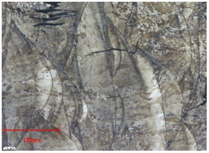
Figure 5. Contrasted specimen. The welded-based microstructure of the manufactured workpiece is clearly visible.
Conclusion
Additional examinations, like hardness testing, require a plane and smooth surface to provide reliable and meaningful results. The materialographic preparation process described above guarantees that the specimen is perfectly suited for hardness testing. ATM offers the Carat 930 for this purpose, a robust instrument for micro-hardness testing and optical evaluation.
The polished surface in Figure 3 reveals a number of cracks. The straight edge on the left was accomplished by milling. The contour of the welded seams is not noticeable. For a more comprehensive examination, the contrast was improved by etching. The etched surface is illustrated in Figure 4. It has more cracks and the colored spots show over-etched areas close to several cracks because of etchant residues.
The welded seams, which have different dimensions, are properly visible. The layer-by-layer deposition method effectuates heat treatment of the subjacent layer. A heat affected zone (HAZ) is formed and causes an alteration in the microstructure, impacting the specimen’s properties. For instance, the hardness may be decreased, causing mechanical stress. As layers of varying hardness are placed one on top of the other, the mechanical stress constantly increases and may result in so-called secondary cracks. A reason for the development of primary cracks is cooling gradients during deposition. Figure 5 illustrates a magnification of single welding beads and their matching HAZ. Hardness testing can expose the differences in hardness of the deposited layers.
References and Further Reading
1. Fraunhofer IWS, Additive Manufacturing, 2016, www.isam.network

This information has been sourced, reviewed and adapted from materials provided by QATM GmbH.
For more information on this source, please visit QATM GmbH.