Flicker is attracting more attention from lighting designers and manufacturers, as well as the standards and specification community. The potential to quantitatively characterize flicker is becoming important for specifying the correct product for risk sensitivity and for a given application.
Image Credit: FlashMovie/Shutterstock.com
IEEE PAR1789 compliance will be vital for LED manufacturers in the near future, both in terms of managing health risks and ensuring compliance. The US DoE suggests that lighting manufacturers and testing laboratories must characterize lighting products for flicker and report the metrics on datasheets.
This article serves as a guide for LED manufacturers who are interested in knowing the causes of flicker, how it can be determined, and how to apply IEEE PAR1789 to their measurements.
Why is Flicker a Concern?
All traditional light sources modulate their luminous flux and intensity to a certain degree because these sources normally use power from AC mains sources.1 This quick variation in the intensity of light source is called flicker, shimmer or flutter.
For LED sources, the amount of flicker is usually determined by the LED driver or, if present, by the driver and dimmer pairing. Products that are more likely to flicker include LEDs dimmed with phase cut dimmers, internal lamp LEDs on some electronic transformers, DC LEDs with simple/inexpensive drivers, AC LEDs, and LEDs with Pulse Width Modulation drivers.2
Flicker has become a concern as LED lighting products grow in popularity. It is acknowledged that light sources with low-frequency flicker, such as 3-70 Hz, can have severe neurological outcomes, including triggering epilepsy in some people. 100 Hz frequencies, which arise with 50 Hz power in Europe, can lead to migraines and headaches. Other problems include eyestrain, blurred vision, fatigue, reduced visual-task performance, distraction and increased autistic behaviors.
Often, an observer indirectly detects flicker when a flickering light or an object lighted with flickering light moves close to the gaze (stroboscopic effect) of the observer; or when the gaze of the observer is moving close to the light or object (phantom-array effect). Either of these effects can be dangerous.
For instance, stroboscopic effects may result in the apparent stopping or slowing of motion of machinery in an industrial setting, whereas phantom-array effects can be disturbing to some people while driving at night. Flicker may cause a physiological effect, whether it is apparent or not.
Lighting applications where flicker is a threat include offices, schools, hospitals, and wherever video equipment is employed (as the contact between flicker and frame-capture rates can create distracting images).2 Flicker is less significant in industrial and sports complexes using 3-phase electrical systems, parking lots and on roads, and it can be required in some situations such as in nightclub lighting systems and for bicycle warning lights.
How Do You Measure Flicker?
There are four factors that can describe the periodic waveform that normally characterizes flicker: the shape or duty cycle (the ratio between the period of a rectangular waveform and the pulse duration), the average value over a periodic cycle (the DC component), amplitude modulation (the difference between its minimum and maximum levels over a periodic cycle), and periodic frequency (the several recurring cycles per second).1
Percent flicker and flicker index are the two most commonly employed metrics for quantifying flicker. The benefit of percent flicker is that it uses a 0 to 100% scale (this is also known as Michelson contrast or peak-to-peak contrast).3
The benefit of the flicker index is that it uses a 0 to 1.0 scale; however, it is not well recognized and not used very frequently. Both these techniques are based on the analysis of single cycle of the periodic waveform and do not form any frequency component. Flicker index can form variation in duty cycle or waveform shape for rectangular waveforms.
Applying IEEE PAR1789 to Flicker Measurements
One should know both the flicker modulation (%) and its frequency while applying flicker measurements to IEEE PAR1789. Depending on whether the frequency range is above 90 Hz or below 90 Hz, a different equation is used and, besides this, two separate levels of allowed flicker can be determined.
‘Allowed’ flicker modulation at a particular frequency can be determined to a No Observable Effect Level (NOEL, the blue line in Figure 1) or a level of low risk (the red line in Figure 1). The NOEL level is a safe zone at which point the flicker is considered fully safe according to IEEE PAR1789, whereas the low-risk level describes a flicker level where adverse reactions are unusual.
The following equations can be used to calculate the NOEL level and low-risk level above and below 90 Hz:
Below 90 Hz
|
Max % Modulation ≤ Flicker Frequency x 0.025
Max % Modulation ≤ Flicker Frequency x 0.01
|
Above 90 Hz
|
Max % Modulation ≤ Flicker Frequency x 0.08
Max % Modulation ≤ Flicker Frequency x 0.033 |
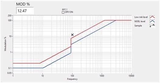
Figure 1. The low-risk level and NOEL lines showing the relationship between flicker frequency and modulation. Note the jump in the trend at 90 Hz. Image Credit: Admesy
From this standpoint, it is very clear that simply assessing the quality of a light source based on the maximum modulation itself, does not give any information without also taking the frequency of the flicker into consideration.
Devices for Automated Flicker Measurement
Admesy provides products and support to perform flicker measurements according to IEEE 1789 flicker recommendations. The company’s Asteria light meter can detect flicker at high sample rates (up to 186,567 samples per second).4 It is developed for in-line use with incorporated calculating power, and is available in different configurations: the lens-based system can measure luminance [cd/m2] and flicker, whereas the cosine corrector configuration allows luminous intensity [cd], illuminance [lux] and flicker measurements. In addition, fiber versions are available to connect to lens systems, remote cosine correctors, or connect to integrating spheres.
Recently, the US Department of Energy’s Solid State Lighting Program tested the Asteria. 1 It discovered that the meter measured flicker-performance characteristics and metrics and light-intensity waveforms similarly to the reference meter selected as an accuracy benchmark. The Asteria functioned well under long-duration conditions (of at least 1 second), and short-duration conditions (measurement time set to 100 ms).
The Cronus spectro-colorimeter provides high sample rate and spectral measurements with just a single device for combined spectral and flicker measurements. It is the world’s first spectro-colorimeter that combines a VIS spectrophotometer and a tri-stimulus colorimeter together.
This unique combination enables the user to select between light, high-speed color, and flicker measurements of the colorimeter and detailed spectral information of the spectroradiometer. The Cronus spectro-colorimeter is suitable for lighting applications where both accuracy and speed are required. It is available in a lens, fiber and cosine corrector version.
Admesy is a world-leading specialist in the field of light measurement and welcomes any additional questions on the application of IEEE PAR1789 to the specific industry.
References and Further Reading
- https://energy.gov
- https://energy.gov/sites/prod/files/2015/05/f22/miller%2Blehman_flicker_lightfair2015.pdf
- https://www.admesy.com/
- https://www.admesy.com/product/asteria/
- https://www.admesy.com/product/cronus/
This information has been sourced, reviewed and adapted from materials provided by Admesy.
For more information on this source, please visit Admesy.