Abstract
Synroc technology by ANSTO has been designed to supply a secure, safe matrix for the final disposal and immobilization of radioactive waste. Synroc technology will be utilized to control radioactive waste from the creation of the radioisotope Molybdenum-99 (Mo-99).
This article will describe the different stages of the process development with direct reference to calcination, a thermal treatment technology and main element of the Synroc methodology.1-2
The rotary thermal processing system comprises of: an optimized modular design of components for easy remote maintenance in a hot cell, compliancy with hot cell radioactive environment standards for maintainability, reliability and safety, and a cutting-edge heating element design for ease of remote maintenance and operation and enhanced robustness.
Along with the thermal treatment of waste from the production of nuclear medicine, this technology offers solutions for a range of nuclear materials processing applications such as the de-nitration of Uranyl nitrate, oxidation of UO2 powder, pellets, and swarf to U3O8, sintering UO2 pellets for reactor fuel rods, and the hydro-fluorination of UO2 pellets. The article will additionally outline thermal processing solutions for a variety of nuclear applications.
Introduction
Waste management from the creation of Molybdenum-99 nuclear medicine is an important international concern for both producers and regulators.
ANSTO’s aim is the conversion of all intermediate-level liquid waste with alkaline chemistry from its isotope production into a hard-wearing solid waste form that adheres to the regulatory standards for disposal and storage.
A key element of ANSTO’s strategy is to employ technologies that increase waste loading inside a form of waste that is long-lasting for either deep geological or near surface repository disposal and storage. ANSTO has designed a modular system that combines multiple technologies that have been verified at a scale relevant to industry.3
The engineering design has been refined to confirm the reliability and maintainability of the plant for nuclear materials processing.
Thermal process technology using a rotary tube furnace is not only essential to both particle and phase formation, but additionally affects the efficacy of Hot Isostatic Pressing (HIP) processing downstream and in the end effects the longevity of the end waste product.
Combining both waste form additive and liquid waste during the procedure causes the production of a free-flowing powder (comprising of ~20 wt.% water) that is highly homogeneous and is fed to the calciner. In the calcination step, the residual water inside of the powder is extracted with some densification and phase formation also arising.
The process flowsheet for the conversion of liquid waste into a solid durable waste form is outlined below in Figure 1.
Powder processing is the first step, where intermediate-level waste is mixed with an additive customized to the waste composition. A thin-film evaporator converts this liquid mixture into a granulated powder and pours the powder inside a hopper for thermal processing.
A calcination stage is performed on the powder containing the radioactive waste inside of the rotary tube furnace, remotely adjusted to handle radioactive powder. Calcined powder freely roams to a metering column where the material is reproducibly filled into a stainless-steel canister for HIP.
The canister is sealed and evacuated before the HIP procedure. HIPing is the next stage in the creation of a durable waste form, which arises when pressure and heat are applied at the same time to create a dense inorganic compact out of the powder. The final volume of the waste package is decreased by this process.
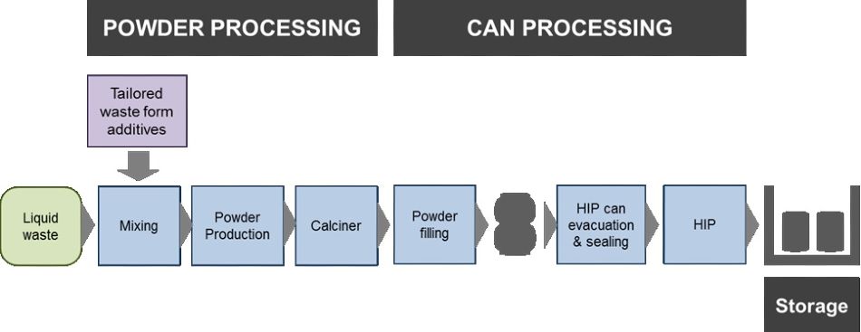
Figure 1. The Synroc Process flowsheet for intermediate liquid level waste treatment. Image Credit: Harper International
Discussion
Harper International was commissioned to plan, devise, and test performance via factory acceptance testing of this important powder processing technology outlined in Figure 1 after a global tender process by ANSTO.
Two rotary calciners were produced: One for the Engineering Demonstrator at the ANSTO facility and the second for the Synroc Waste Treatment Plant (SWTP). These rotary calciners had several specifications due to the hot cell surroundings. A cooperative approach was used to assess the development and design of the furnace’s key characteristics.
In part, the effectiveness of this project was the result of the collaboration between each team. The desired functionality of the rotary calciner inside of a shielded hot cell enclosure created several of the novel system requirements.
Specific requirements for materials and their construction, remote serviceability and high system integrity presented an intricate system design challenge. The system had to facilitate remote operation, disassembly, reassembly, and service via access ports through a shield wall on one side of the rotary calciner system.
The efficiency of remote reassembly and disassembly was crucial for restricting personal time inside the service location and any possible plant downtime. This, alongside the ease of substituting parts, was thought to be crucial for an efficient turnaround.
Along with the exact requirements for remote serviceability, a quality plan customized to the project was created in line with a Nuclear Quality Assurance-1 (NQA-1) standard including documentary evidence.
This plan was clear, complete, highly structured, and thoroughly adhered to. The key aspects of the plan were: counterfeit inspections, certified COTS materials, certified performance testing, certified third-party NDE inspection, 100% dimensional inspections, certified manufacturing processes like welding, certified materials, and Inspection and Test Plans (ITPs).
Each of the materials was systematically handled, being well-identified, segregated, and dispositioned, with their availability and status to manufacturing being explicitly specified. The process was tightly controlled and the system was verified as being compliant with the requirements as a result of strictly following the quality plan.
Requirements for the Rotary Calciner System
The aim of the project was to devise and produce rotary calciners that were fully tailored to the nuclear hot cell environment. This rotary calciner is installed inside of the powder production system. Designing, conceptualizing, and providing a dependable system for inclusion inside of a hot cell was a key challenge.
There were several limitations placed on the design regarding accessibility, materials used in construction, and space. A main requirement of the design was the incorporation of gloved ports for maintenance and operation to access through a shield wall on one side.
Rotary kilns are utilized for processing several types of free-flowing materials, powder, granular. Figure 2 demonstrates the design of a typical rotary system. The feed material is moved into the rotary tube via the system’s feeder at the front end. The inclination of the alloy tube normally ranges from 0.5 to 5 degrees.
Along with the tube rotation, the tube angle distributes the material across the length of the tube and allows the residence time to be controlled. This enables the mechanism to move the material into and out of the heating area.
The powder material travels to the discharge hood at the tube exit, where it is dispensed to the product collection equipment via a chute. The rotary calciner system was constructed with atmosphere seals on the exit and entrance of the rotary tube to divide the room air from the process gas inside the rotary system.
The process gas was funneled into the exit chamber and moved through the process tube in a counter-current direction to the entrance chamber. The discharge hood and the feeder were produced with seals to stop the egress of dust or kiln atmosphere from escaping the system.
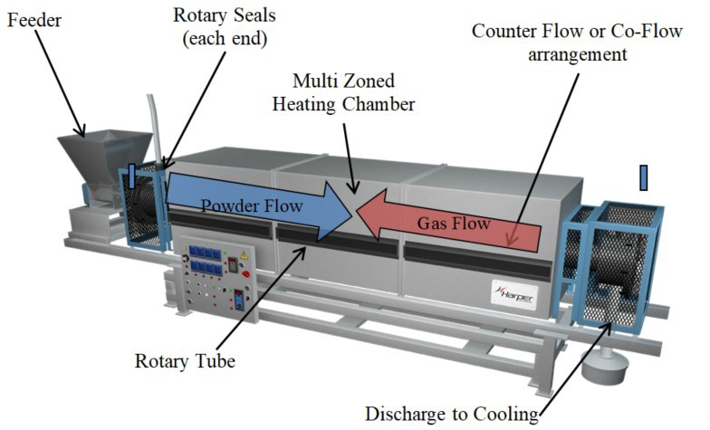
Figure 2. Typical rotary system major elements. Image Credit: Harper International
The process is kept inside of a shielded hot cell for the SWTP implementation of the rotary calciner, with concrete walls of 800 mm to shield against gamma radiation emission from fission product decay.
A number of internal enclosures are held within the hot cell, one of which houses the calciner. ANSTO has devised a system for tall form powder production where additive and liquid waste entering the enclosure travels and converts into a free-flowing powder utilizing gravity to direct the entry hopper into the rotary calciner.
Before any arranged maintenance, feedstock materials including radioactivity will be run out which reduces the radiological inventory before servicing occurs. Remote serviceability to the rotary calciner was required with restricted access via the shield wall due to the limited access to the hot cell environment.
To achieve this, the subcomponents of the rotary system were considered for remote extraction and transport to a different area of the plant for maintenance.
The key subcomponents were the exit hood, exit trunnion, heating elements, entrance hood and seal, alloy process tube, entrance trunnion and dive motor, and screw feeder.
All the subsystems were constructed to be remotely removed inside the hot cell and transported to an area where maintenance could be carried out.
Figure 3 outlines the key subcomponents for remote replacement and removal. These subsystems could additionally be used as important spare parts, so substitutions of the parts could offer a method of efficient servicing.
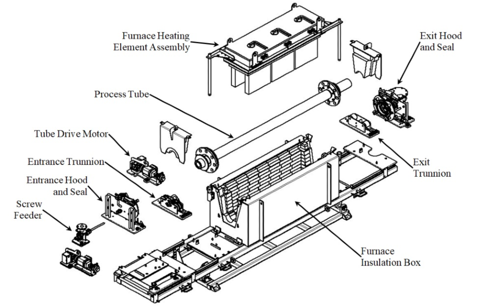
Figure 3. Rotary calciner remote disassembly. Image Credit: Harper International
Project Delivery Strategy
A stepwise approach was utilized to ensure adherence to the overall design intent and the written specification. During the engineering stage, each subcomponent was tested for compliance with the plan for remote disassembly, construction materials, and eventual subcomponent evaluation and testing.
A ‘Quality’ Foundation to Ensure a Successful Project
Due to its complexity, there were highly specific requirements for the performance of the system and execution of the project.
This was the most stringent project that Harper had ever accepted which meant that a quality plan customized to the project was produced with the collaboration and guidance of ANSTO.
A critical feature was the development of subassembly level inspection and test plans and the creation of vendor and internal supported processes to assist them before designs were released to manufacturing and procurement.
For each key sub-assembly, individual ITP’s were devised and adhered to. For instance, a structural weldment would include these major elements: dimensional inspection reports for manufactured components, material certificates, certified inspectors, welders, and weld procedures, and highly detailed drawings with all weld and NDE call outs, and a weld map.
For important purchased components, the ITPs would provide a certificate of conformance to specifications from the manufacturer, along with calibration certifications or test performance results where appropriate.
In other examples, like the gearbox, accurate scope splits and relevant specifications were determined, performed, and confirmed before products were released to the assembly stage.
System level function testing at the general assembly level was also carried out as a requirement of the client’s Factory Acceptance Testing (FAT) and the ITP to gain shipping approval and validate performance to requirements. In the last stage, a detailed audit of all documentation was carried out to ensure this methodology was carried out universally and was documented.
Advanced Rotary Features
Several examples outlining some of the solutions and challenges of the rotary calciner for hot cell environments are outlined below. This is not a comprehensive list of the advanced features, but instead outlines several advantages of the rotary calciner.
Advanced Heating Element Design
The heating element design had a few extra requirements for the hot cell environment. The heating system needed rugged and redundant heating components that were capable of remote reassembly and removal.
During the construction and design of the advanced heating component, each of the special requirements were addressed and refined. The advanced heating element was constructed with a remote stand to be placed after removal from the rotary kiln. The heating element is positioned into the rotary kiln stand by utilizing locating pins.
The terminal connections were located for access through glove ports from the operator access side. A redundant part was included in the element design so the system would not be prevented from functioning by the failure of a single component. Detailed specifications, a robust design for element manufacture, and confirmed repeatability allowed for a repeatable result during assembly.
This advanced heating element design was correctly assessed for ease of remote maintenance and operation at the factory before being shipped to the process plant facility.
Rotary Tube Drive System
The rotary tube drive system was needed to offer various speeds of rotation to the rotary furnace, to adhere to material of construction limitations, and to be remotely removable for maintenance.
A design and refine strategy was used in the development of this system. Design reviews created with 3D modeling for evaluation of accessibility were assessed.
Vendor feedback on the particular subassemblies and components meant that updates and modifications to the system were performed for increased functionality. The shared work of ANSTO and Harper ensured compatibility with the hot cell lifting system and the shield wall which was being produced alongside the rotary calciner.
The majority of subcomponents were constructed to be located on pins and secured in position with a tailor-made hand locking device, accessible outside of the shield wall access. In the example of the rotary tube drive, further steps were necessary for connection to the drive coupling on the entrance trunnion subassembly.
A gear on the rotary tube was engaged by the entrance trunnion system. The correct positioning of the gear and coupling system is crucial for the rotary drive system to properly operate. The entrance trunnion system is initially positioned onto the base beam for the system to be assembled.
The crane lift support brackets were constructed at the center of gravity and were strategically positioned to ensure movement via the shield wall access ports. Guiding pins are initially used to position the entrance trunnion, which is then secured into place with the tailor-made locking pins.
The next subcomponent for assembly is the drive. The drive is positioned utilizing the lift support brackets located at the center of gravity. The drive was able to move forward to engage the coupling on the entrance trunnion subassembly as the placement was on a slot.
The locking pins were engaged after the drive system was in the proper position. The tube assembly would then be positioned on the trunnion system to engage the gearing. From detailed design to conceptual design, a sequence of design reviews were performed alongside a stringent assessment of the ergonomics and accessibility of the positioning hardware.
3D modeling tools were used to picture the remote assembly and disassembly as the detailed design advanced. Selectively devising and engineering precision custom alignment and locking elements and their subsequent evaluation provided a basic yet dependable multi-subassembly remote construction.
It was further demonstrated that subassemblies were interchangeable between the two rotary calciners which inspired confidence that future spare part purchases could be assembled in this setting. A thorough evaluation of the construction materials was required for the gearbox to make sure that these materials were compatible with gamma radiation.
A procedure was also required for the gearbox to remove materials that were non-compliant (particularly grease). An ITP was produced for this procedure to confirm that all non-gamma compliant materials were eliminated, reassembled, and cleaned. A dedicated gamma radiation resistant grease was then used to coat the system.
After a detailed task of testing capabilities and then relating those to the requirements of the project, accurate scope splits and relevant specifications were executed, applied, and confirmed before the product was released to the next vendor. An assessment was performed for each subassembly involved in remote disassembly and assembly. Highly specific ITPs were produced in this process.
Factory System Testing
Factory acceptance testing (FAT) was performed once the construction of the rotary calciner was complete. A mock shield wall (Figure 5) was constructed with the opening planned in the SWTP to test the novel elements of the remote disassembly and reassembly that was required.
This mock shield wall was utilized for the investigation of all remote operations. Total reassembly and disassembly was carried out for the factory acceptance testing before shipment. It was then possible to precisely adjust the features and procedure.
The assembly of the heating component is outlined in Figure 6. Note the proximity of the access locations to the terminal connections. Simulated maintenance, assembly, and operation were effectively performed for both furnaces within the factory acceptance testing.
During the simulation, the furnaces were entirely assembled and then disassembled much faster than the target time before shipping. A less than 10% variance was reported in timing when comparing the two furnaces. Insights and confidence were gathered with the furnace along with the efficacy of the mock shield wall access areas.
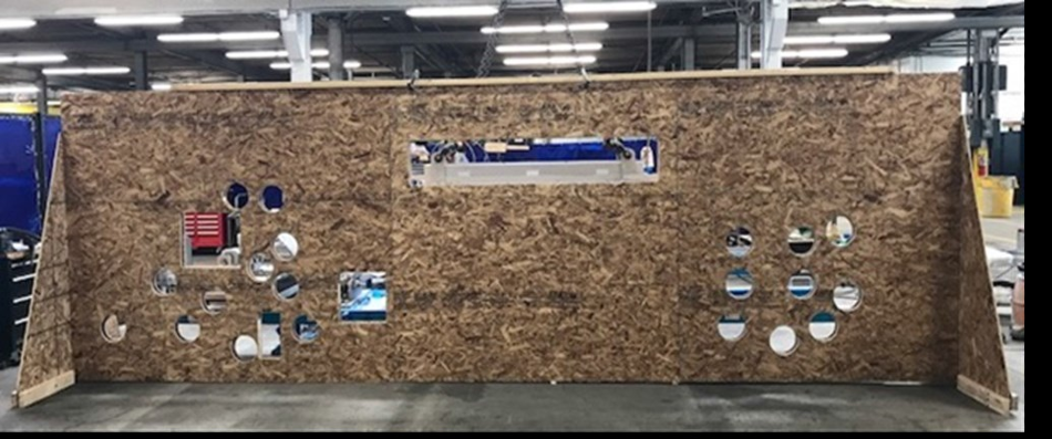
Figure 5. Mock shield wall for rotary calciner testing. Image Credit: Harper International
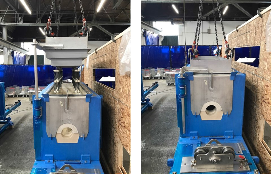
Figure 6. Assembly of the heating element into the rotary kiln. Image Credit: Harper International
Testing of Rotary Calciner at the Engineering Demonstrator Facility
To enhance the technical maturity of the Synroc technology, a second rotary calciner with a customized design and the same modular design was installed into its inactive engineering demonstrator to validate, develop, and test the operational process parameters for the production of powder (Figure 7).4
The rotary calciner has been installed into the plant with success, creating powder that fulfills the standards for downstream processing. Figure 8 presents a simulant of powder flowing inside of the rotary tube.
Feed rates of 3.5 kg per hour have been attained which meets the technical requirements for processing. An additional unit with the same construction and design will be commissioned inside the final waste treatment plant after the building is completed.
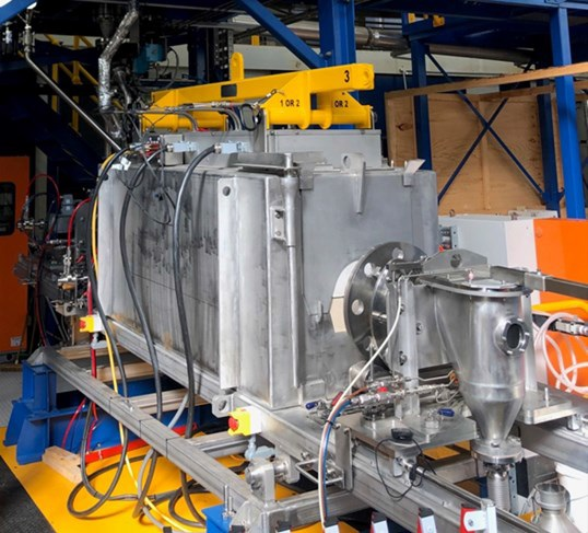
Figure 7. Harper Rotary Calciner within the ANSTO Synroc Demonstration Plant. Image Credit: Harper International
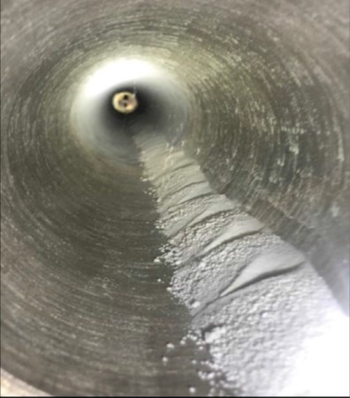
Figure 8. Calcined powder with waste stimulant from the unit integrated within Synroc’s inactive engineering demonstrator. Image Credit: Harper International
Calciner Installation, Integration and Commissioning into Final Plant
The construction of the final waste treatment plant is developing with the handover of the building predicted to arise in late 2020. The layout of the plant and configuration of equipment for the powder production stage, which includes the second rotary calciner, has been configured and designed inside of the shielded enclosure founded on the inactive engineering demonstrator.
After handover of the building, fit out of the equipment for the waste treatment facility and plant will arise before the commissioning phases.
Technology Solutions for Nuclear Materials Processing Applications
The design of the rotary calciner for shielded hot cell enclosures outlined in this article is a sophisticated example of how clients and suppliers can collaborate to execute technical solutions for waste management projects.
Along with the treatment of solid and liquid wastes from the production of radioisotopes, this thermal process technology can be applied to a wide selection of legacy nuclear wastes where expertise can solve complicated processing needs through customized rotary calciner design concepts.
Rotary calciners can additionally be a dynamic testing device for many university and government lab-based research projects. Further applications for rotary calciners are in processing where toxicity or dust containment is a key necessity, the hydro-fluorination of UO2, and the de-nitration of uranyl nitrate.
A further widespread application for this thermal technology happens at nuclear fuel fabrication plants that recycle damaged off spec fuel powder, swarf, and pellets, which are then processed in an oxidative environment to change the waste UO2 into U3O8 in restricted access locations or when contained within hot room and hot cell settings.
This material is then reprocessed back to green UO2 pellets for feed into the sintering stage in the cycle of fuel fabrication. This thermal technology can also be applied to nuclear fuel fabrication where kilns and hydrogen reduction atmosphere pusher tunnel furnaces are used for sintering green UO2 pellets which are then utilized in reactor fuel rods.
Conclusion
The rotary calciner from Harper for hot cell locations offers a successful technical solution for the calcination stage in the treatment of streams of liquid waste from radioisotope production. The rotary calciner has been manufactured to fully combine with Synroc’s modular process technology. The effectiveness of this project was the result of numerous considerations.
The mutual collective approach between ANSTO and Harper International during the system, design, and build testing to meet the written requirements along with the overall design intent addressed the technical disadvantages of the maintenance of equipment and the confinement of waste products in a hot cell environment.
Along with the design challenges, stringent adherence to the high-quality specifications along with the range of construction material standards created a project that achieved and went far beyond the relevant, project-specific quality standards.
During the factory acceptance testing, the remote serviceability, operation, along with remote reassembly or disassembly of the rotary calciner was effectively verified with the access limitations predicted within the SWTP.
The practical physical restrictions and attention to the details of the service environment produced in a system that was efficient to use for these maintenance and operational functions. This rotary calciner produced for hot cell environments has been commissioned within the Engineering Demonstrator at the ANSTO facility.
Inactive material was run through the calciner by the demonstrator facility, testing the design and determining process conditions for its subsequent implementation. The processing of radioactive material inside of ANSTO’s SWTP utilizing the rotary calciner is scheduled for 2021.
While the designed calciner is predicted to have exceptional process capability, the design and size of these modular thermal processing units create an opportunity for the expansion of their capacity. This increase in capacity can be attained with several parallel lines. This solution provides a low-risk scale-up while reducing the quantity of process material inside the service area.
Acronyms
NDE: Non-Destructive testing
ITP: Inspection and Test Plans
NQA-1: Nuclear Quality Assurance-1
COTS: Commercial Off-the-Shelf
FAT: Factory Acceptance Testing
SWTP: Synroc Waste Treatment Plant
HIP: Hot Isostatic Pressing
Acknowledgments
Produced from materials originally authored by Peter Witting1, Jason Gwin1, Tom O’Connor1, Rohan Holmes2, Amanda Abboud2, William Townsend2, Michael Deurra2, and Gerry Triani2 from;
1. Harper International Corporation
2. ANSTO
References and Further Reading
- D.J. Gregg, E.R. Vance, “Synroc tailored waste forms for actinide immobilization”, Radiochim. Acta., 105(11), 907- 925 (2017)
- M.L. Carter, H. Li, Y. Zhang, E.R. Vance and D.R.G. Mitchell “Titanate ceramics for immobilization of uranium rich radioactive wastes arising from 99 Mo production”, Jnl of Nuc Mat, Vol 384 (3), 322-326 (2009)
- R. Holmes, D.J. Gregg, E.R. Vance, M. Smith and G. Triani; “Synroc Waste Treatment Facility for Fission-based Molybdenum-99 Production” Waste Management Symposium, Phoenix, Arizona, USA (2019)-19335
- R. Holmes, A. Abboud, B. Bigrigg, D.J. Gregg and G. Triani; “ANSTO Synroc’s Engineering Demonstrator” Waste Management Symposium, Phoenix, Arizona, USA (2019)-19342

This information has been sourced, reviewed and adapted from materials provided by Harper International.
For more information on this source, please visit Harper International.