The method of Chemical mechanical polishing/planarization (CMP) is commonly employed in the microelectronic industries to smooth surfaces with a blend of chemical and mechanical forces. This method employs a harsh and corrosive slurry to aid the planarization of the exterior of a wafer.
The CMP slurry is an intricate combination of nanosized abrasive particles and additional chemicals, including pH adjusters, surfactants, organic acids, complexing agents and oxidizers. The abrasive’s particle size distribution is a vital parameter influencing the whole process in multiple ways. The abrasive mean size and distribution width affects the material removal rate (MRR).
The occurrence of large particle counts (LPCs) can have a harmful impact on yield by producing scratches and defects1,2. LPCs are the right side (bigger) tail of the distribution and are frequently termed as the particle concentration in counts/ mL >1 µm, however, the precise size range differs by application.
Various analytical methods are employed for gauging mean size and tails. No individual instrument can deliver all desired data across a whole dynamic range. Dynamic light scattering (DLS) is often utilized to gauge the mean size and single particle optical sizing (SPOS) is employed to measure the LPC tails.
Mean Size vs. Tails
Figure 1 displays the mean size calculated by dynamic light scattering of four abrasives employed in CMP slurries: silica, ceria, alumina, and colloidal silica. The difference in both mean size and distribution width can also be observed in Figure 1.
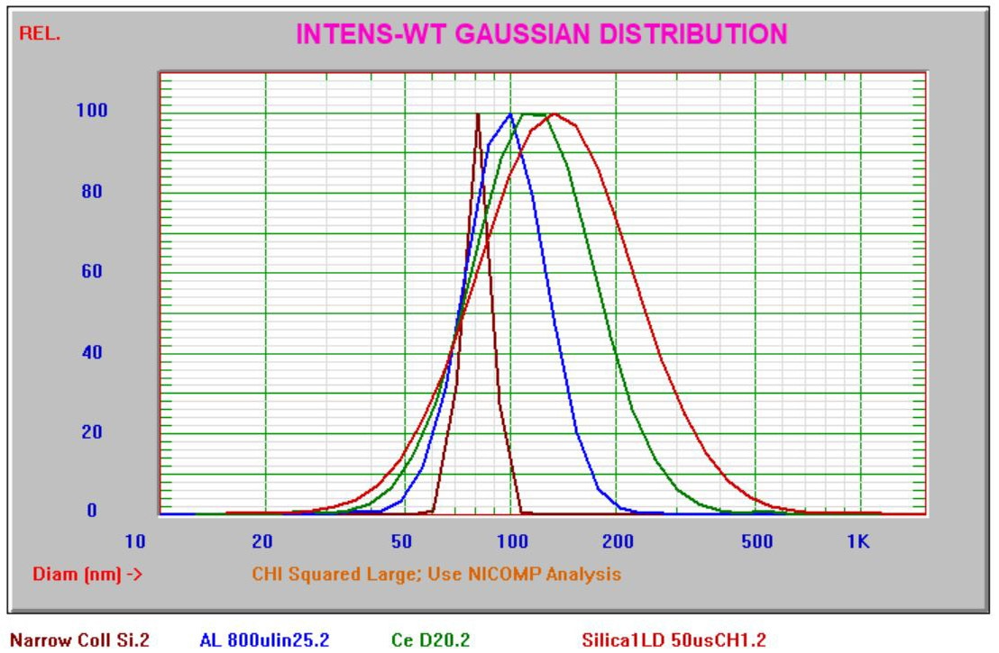
Figure 1. Mean size vs. tails of distribution. Image Credit: Entegris
The mean size data displayed was acquired employing the Nicomp® DLS system. A separate Entegris application note focuses on measuring mean size and zeta potential of CMP slurries.3 The tails4 are usually measured using the method of single particle optical sizing.
The AccuSizer® lab and online systems are utilized by slurry manufacturers, researchers, and in fabs across the globe. This article focuses on laboratory measurements of CMP slurries using the range of AccuSizer instruments. Models employed in the laboratory to measure CMP slurry LPCs consist of the AccuSizer AD, AccuSizer APS, and AccuSizer FX Nano systems.
AccuSizer System Components
All AccuSizer systems are comprised of a sensor, pulse height analyzer (counter), and fluidics in order to dilute and transport the sample. The 1024 channel counter employed is the same that is used for each system and completes the task of transforming pulses from the sensor into particle size and count using a calibration curve. Two sensor models, the LE400 and the FX Nano, are selected subject to the sample needs.
The LE400 sensor, Figure 2, measures from 0.5–400 µm and records every particle coming through the system, delivering a 100% counting efficiency. This sensor employs a collimated laser beam and both light obscuration and light scattering detectors to deliver a very wide dynamic range. The concentration threshold is roughly 10,000 particles/mL.
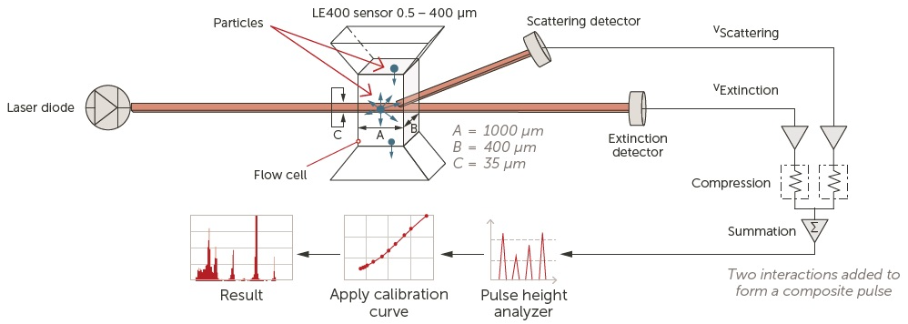
Figure 2. LE400 sensor and operation. Image Credit: Entegris
The FX Nano sensor, Figure 3, measures only at the very center of the flow cell, employing a focused laser beam. This sensor needs a proprietary algorithm to transform particle pulses into sizes due to the focused beam and non-unique pulse-to-particle size relationship. The FX Nano sensor measures as low as 0.15 µm and can measure at much larger concentrations (~106 particles/mL). A blend of FX Nano and LE400 sensors provides a dynamic range of 0.15 – 400 µm
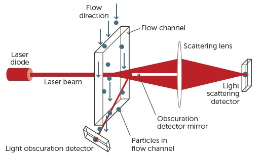
Figure 3. FX Nano sensor. Image Credit: Entegris
Two dilution fluidics choices are offered to dilute the sample, control flow rate through the sensor, and flush to cleanse the system after each measurement. Following this, the software assesses the real concentration in the initial non-diluted sample over as many size channels the user determines.
AccuSizer AD System
The AccuSizer AD system is a single-stage exponential dilution system with the LE 400-sensor incorporated. The AccuSizer AD dilution fluidics diagram (not to scale) can be seen in Figure 4.
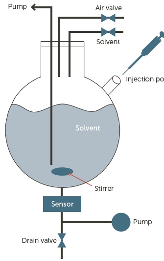
Figure 4. AccuSizer AD system and dilution fluidics. Image Credit: Entegris
The dilution chamber is injected with a sample and dilution begins instantly. Solvent (DI water) is added to the chamber at the same flow rate that the sample is drawn through the sensor. The concentration is observed, and the measurement commences when the concentration is less than the coincidence limit of the sensor. The system is automatically flushed to an adequate background level following the completion of measurement.
AccuSizer APS System
The AccuSizer APS system combines both single and two-stage dilution fluidics in one system. The AccuSizer APS two-stage dilution fluidics diagram can be seen in Figure 5.
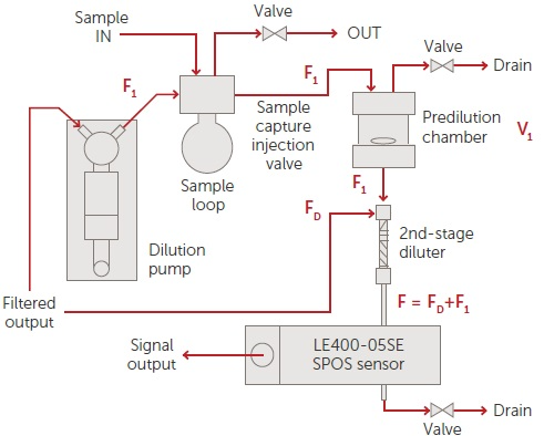
Figure 5. AccuSizer APS two-stage dilution fluidics. Image Credit: Entegris
The AccuSizer APS system may be operated in numerous modes. When running in two-stage dilution, the sample is drawn into the sample loop with volume VL. The initial stage of dilution begins when the sample loop is injected into the dilution chamber with volume V1. The first stage of dilution is V1/VL. The following stage of dilution ensues when the diluted sample flow F1 combines with filtered water FD. The entire flow F flows through sensor for analysis.
This method enables a stable concentration throughout the duration of the measurement. To better visualize the distinction between these two methods of autodilution - AccuSizer AD vs. APS systems - a contrast of counts vs. time throughout data collection can be seen in Figures 6a and 6b.
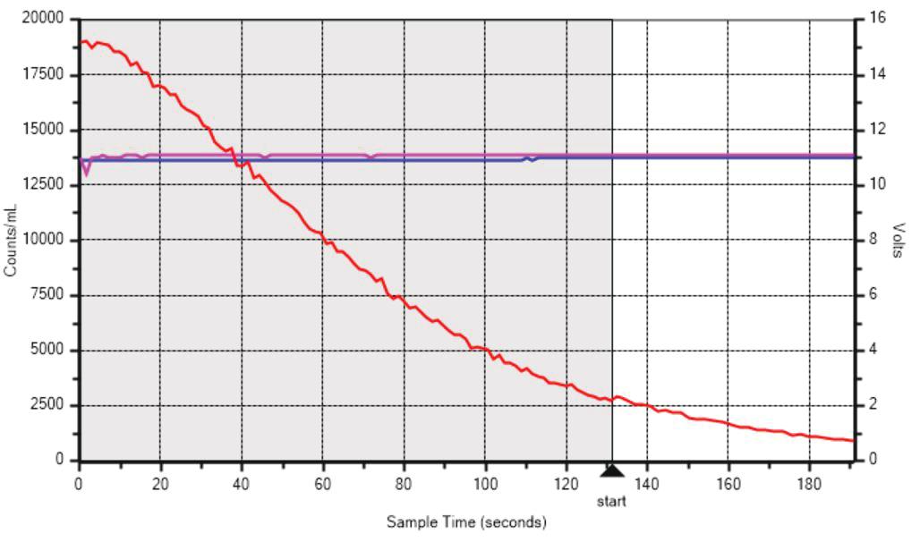
Figure 6a. AD system dilution. Image Credit: Entegris
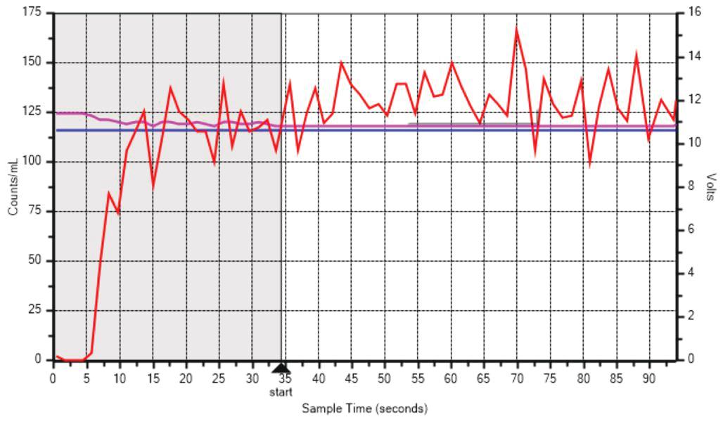
Figure 6b. APS system dilution. Image Credit: Entegris
Plot Interpretation
Source: Entegris
| . |
. |
| X axis |
Sample Time in seconds |
| Left Y axis |
Particle Counts/mL |
| Red line |
Counts/mL vs. time |
| Right Y axis |
Sensor voltages |
| Pink line |
Scattering voltage |
| Blue line |
Extinction voltage |
| Grey area |
Dilution time |
| White area |
Measurement time |
The time history graph in Figure 6a, is from a concentrated ceria slurry measured on the AccuSizer AD system. The concentration (counts/mL) starts extremely high a prior to measurement beginning, over 120 seconds of dilution time is necessary. The measurement then happens while the sample is still being diluted.
Figure 6b shows the time history graph from a silica CMP slurry in which the concentration is satisfactory at the start of the sequence, however the measurement does not take place until after a 30 second equilibration time. The measurement then continues at a steady rate of counts/mL. This approach is favored for samples with smaller count rates in the LPC range so that the total number of counts accumulated is statistically effective for precise, repeatable results.
AccuSizer FX Nano System
Incorporating both the LE 400 and FX Nano sensors, the AccuSizer FX Nano system is a single-stage exponential dilution system. The dilution fluidics are similar to what is displayed in Figure 4 and dilution takes places as in the AccuSizer AD system. The sample measurement is created in three collections.
The system initially accumulates data with the FX Nano sensor in low gain (.fyl) plus the LE400 range (.led). Then the system shifts and measures the FX Nano sensor in high gain (.fyh). Following this, the three ranges are collected and the three result files are merged into a single file (.fyc) encompassing the whole dynamic range.
The AccuSizer FX Nano system is perfect for delivering sensitivity down to 0.15 µm across a wide dynamic range. Some extremely clean colloidal silica slurries are analyzed best utilizing the FX Nano system, where the sensitivity to 0.15 µm is necessary to gather enough counts to be statistically valid. Additionally, this system is employed internally within Entegris for testing filter retention of CMP slurries.5
Example Results
The AccuSizer AD system was employed to measure KLEBOSOL™ 1501 colloidal silica CMP slurry prior to and after filtration through an Entegris Planarcap® NMB point-of-dispense CMP slurry filter. In Figure 7 the upstream vs. downstream comparison findings can be seen.
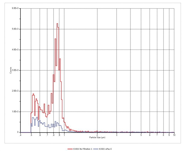
Figure 7. AccuSizer AD system results before (red) and after (blue) filtration. Image Credit: Entegris
This graph displays a spike of LPCs centered close to 0.85 µm being removed by the filtration process. The AccuSizer AD lab system can be utilized to perform a QC check of CMP slurry, which is incoming and as a means for filtration studies to ascertain the best possible filter for a given slurry and process needs. A silica CMP slurry was examined using the AccuSizer APS system functioning in two-stage dilution mode.
A standard result can be seen in Figure 8, which is the result from the run time data displayed in Figure 6b. The table in Figure 8 demonstrates particle concentration at five user-determined size ranges. This report can be tailored to present and concentrate on results at ranges deemed crucial for tracking LPCs. The concentration displayed is the actual concentration in the original sample before dilution. A comprehensive table of up to 1024 size channels is accessible, as are numerous report formats.
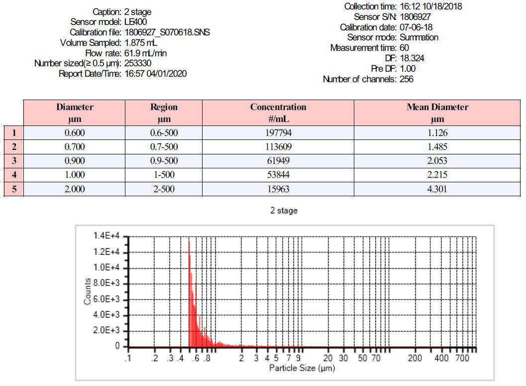
Figure 8. CMP AccuSizer system APS results. Image Credit: Entegris
A dual sensor AccuSizer FX Nano system was employed to analyze an alumina CMP slurry examined on during an internal Entegris training session. After being pre-diluted 1000:1, the sample was then analyzed using a 0.5 ml sample loop dispersed into an 11.8 ml vessel volume. For all measurement ranges, a 60 second sample time produced an average of roughly 200,000 total particles counted for each analysis. The sample was analyzed by four separate Entegris field application engineers and the outcomes from four individual measurements are displayed in Figure 9 with the Y axis (concentration) demonstrated on a logarithmic scale.
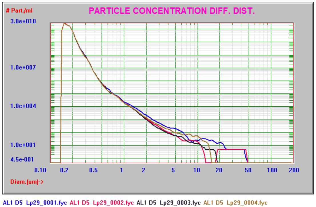
Figure 9. Alumina CMP slurry AccuSizer FX Nano system results. Image Credit: Entegris
These independent results show brilliant reproducibility. The four overlays are almost impossible to distinguish under 1 µm. The variation observed above 10 µm is because of the poorer statistics at bigger sizes. As these are actual sample concentration values calculated following a 1000:1 pre-dilution and exponential dilution by the fluidics, the differences greater than 10 µm may be from single particles.
Conclusions
The variety of AccuSizer laboratory particle size and count analyzers are well-suited for testing for LPCs in CMP slurries. The benefits of the AccuSizer system consist of sophisticated auto dilution fluidics, the largest dynamic range (0.15–400 µm), advanced reporting possibilities, and wide approval by both CMP slurry producers and end users in the fabs.
Entegris suggests sending slurry samples to application labs for evaluation and review so the optimum system design for specific slurries and customer needs can be recommended.
References
- Remsen, E. et al., Analysis of Large Particle Count in Fumed Silica Slurries and Its Correlation with Scratch Defects Generated by CMP, Journal of The Electrochemical Society, 153 (5) G453-G461 (2006)
- Kim S.-K. et al, Effect of calcination time on the physical properties of synthesized ceria particles for the shallow trench isolation chemical mechanical planarization process, Journal of Ceramic Processing Research, Vol. 7, No. 1, pp. 53-57 (2006)
- Entegris Application Note – Mean Size and Zeta Potential of CMP Slurries
- Entegris Application Note – Detecting Tails in CMP Slurries
- Entegris Application Note – CMP Slurry Filter Testing

This information has been sourced, reviewed and adapted from materials provided by Entegris.
For more information on this source, please visit Entegris.