Sponsored by MerckJan 4 2021
Plasmonic nanoparticles have special optical properties that can be customized to suit a various applications in the biotechnology1–8 and electronics9–16 industries. Due to their tunability in the near infrared (NIR) light spectrum and biological inertness, gold nanorods (Figure 1), a specific subset of plasmonic nanoparticles, are of interest for biomedical applications.17–20
For the synthesis of gold nanorods, there are multiple techniques, including templating,21–25 electrochemical growth,26–28 and reverse micellar systems.29–30 In this article, the focus is on seed-mediated colloidal growth methods. While there are several published variations on the seed-mediated colloidal growth of gold nanorods,29,31–38 this discussion will outline the familiar approaches developed by Nikoobakht and Murphy.31,39
Seed-mediated colloidal growth has multiple benefits over the previously mentioned methods,41 such as the lack of need for specialized equipment in combination with straightforward scalability – necessary requirements for clinical translation.43–44 While these methods are well-understood, their sensitivity to small changes in reaction conditions can result in a lack of control over the shape, size, purity and aspect ratio of rods from batch to batch.19,33,36–37,44–50 Throughout this review, hoe seed mediated gold nanorod synthesis is discussed and then a detailed discussion presents how best to avoid any common pitfalls.
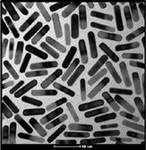
Figure 1. TEM image of typical gold nanorods. Image Credit: Merck Millipore Sigma
Synthesis
Fundamental synthesis follows the work of Nikoobakht and Murphy,31,37,39,51–52 where exact reactant concentrations and volumes are discussed. Briefly, a growth solution composed of cetyltrimethylammonium bromide (CTAB, Prod. No. 52370), silver nitrate (AgNO3, Prod. No. 792276), chloroauric acid (HAuCl4, Prod. No. 254169) and water is prepared. If a multi-surfactant system is necessary for longer aspect ratios, benzyldimethyl ammonium chloride (BDAC) is usually included, although other surfactants such as sodium oleate (Prod. No. O7501) have also been noted.46,53 Ascorbic acid (Prod. No. A92902) is then incorporated to limit the Au3+ to Au1+.
To template further reduction of gold, small gold nanoparticle seeds are then included in the mixing of the solution. The seeds are synthesized via an accelerated reduction of HAuCl4 by sodium borohydride (Prod. No. 480886) in a CTAB or citrate solution. When the seeds have been added, Au1+ is reduced further to metallic Au0, with the surfactants and Ag acting to break the symmetry through preferential deposition on the {110} facets of gold, preventing growth54 and stimulating growth parallel to the {001} plane, resulting in anisotropic gold nanorods.31
Six Common Pitfalls in Gold Nanorod Synthesis
The Importance of Good Synthesis Preparation (1)
Small amendments in overall concentrations, impurities and nucleation sites can lead to considerable differences in particle shape, size and purity, rendering reproducibility a concern. Therefore, successful and repeatable gold nanorod synthesis depends fully upon a meticulously, consistent preparation and correct lab technique.
First, to make sure growth is even, nucleation sites must be well-controlled. As a typical requirement for almost any metallic nanoparticle syntheses, all glassware and stir bars must be cleaned thoroughly with aqua regia55 to eliminate residual metals. Any residual metal will result in undesired pre-nucleation in the growth solution, making controlled synthesis unfeasible.
Throughout the synthesis process all water used, including glassware cleaning, must be 18.2 MΩ・cm ASTM Type I water (frequently known as deionized ultrafiltrated, DIUF, or 'Nanopure™' water). In addition, the lab space should be thoroughly cleaned with limited dust.
Another frequent cause of lab-to-lab variability, or even person-to-person, is the preparation of reagents; even when purchased from the same supplier, minimal changes in impurities from lot-to-lot can severely impact the ultimate product of the nanorod synthesis. For instance, Korgel et al. reported on the effect of the CTAB source on nanorod synthesis.33 It was compelling that the results that indicated trace impurities in CTAB, specifically iodine, are actually necessary for the production of high quality rods.56
Similarly, NanoHybrids has discovered that changing the gold acid source can impact the overall size and longitudinal surface plasmon resonance (LSPR) of the resulting rods. For these reasons, documentation and tracking of reagents must be carried out all synthesis. Whenever substituting reagent lots or sources, pilot reactions should carried out first to identify the new baseline for additional size and shape tuning.
Other considerations to consider include the age and storage conditions of the reagent. For simple reactions and to limit inherent weighing errors, many groups opt to make stock solutions of reactants. Recent work by Murphy et al.38 exhibited that solutions of silver nitrate and ascorbic acid are best prepared fresh due to their sensitivity and vulnerability to photodegradation.
Likewise, the age of CTAB solutions has been known to affect the final product.38 These effects can either be detrimental or potentially leveraged for increased control over reaction kinetics depending on the quantity and scale of reactions a lab produces. Again, good documentation is the key to success.
Aggregation Happens: Rod Instability (2)
One of the most well-known issues that occurs during synthesis is nanoparticle aggregation. Knowing when aggregation occurs is critical as is knowing how to prevent it. It is easy to detect aggregation of nanorods with an absorbance in the NIR spectrum using ultraviolet-to-visible (UV/Vis) spectrophotometry. The key indicator of aggregation is the presence of a 'shoulder' in the extinction spectra. A typically 'good' spectrum is illustrated in Figure 2A. Note the narrow, symmetric shape of the LSPR peak and the high ratio of the LSPR peak to the transverse surface plasmon resonance (TSPR) peak (labeled as L/T, Figure 2A).
Figure 2B exhibits the result of slight aggregation. Note the clear lack of symmetry and right-sided distortion of the LSPR band caused by plasmon coupling in gold nanorod aggregates. Likewise, Figure 2C exhibits particles produced using a dual surfactant system (CTAB + BDAC). While not as clear and obvious as Figure 2B, the asymmetry of the LSPR band and increased full width half maximum (FWHM) indicates significant issues with the synthesis. These include high polydispersity of size and aspect ratio or slight aggregation. These problems are not deep-rooted in all dual-surfactant reactions and, therefore, indicates a failed reaction.
Also, the shape of the TSPR band (BDAC Trans Peak) in Figure 2C should be noted. The additional small shoulder is a result of hair-splitting differences in the shape of the rods themselves, as well as any associated impurities (cubes vs. spheres). This variation in the TSPR band is to be expected even in a 'good' dual-surfactant reaction with a narrow LSPR and high symmetry. A spectrum of nanorods with large amounts of shape impurities (greater numbers of spheres and cubes) is illustrated in Figure 2D and further discussed in pitfall #4. Finally, severe aggregation can be clearly seen by particle precipitation or an alteration in appearance from various shades of red to dark gray or purple, as Figure 2E exhibits.
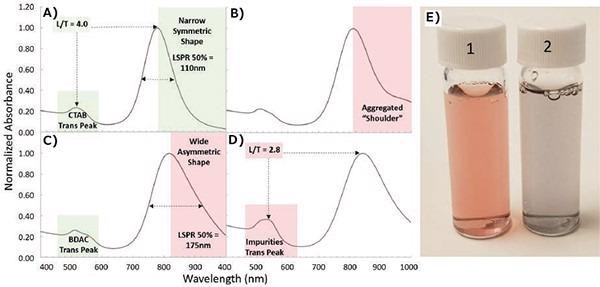
Figure 2. Spotting nanorod aggregation and shape impurities using normalized UV/Vis spectra. A) Ideal spectra of gold nanorods synthesized with a single surfactant (CTAB) is evidenced by a high LSPR/TSPR peak ratio (L/T) and a narrow symmetric LSPR peak. B) Spectra displaying aggregates in a 'shoulder.' C) Spectra of particles synthesized in a binary surfactant (CTAB and BDAC) is illustrated by the shape of the transverse peak. Wide size distribution is indicated by a wide asymmetric LSPR peak on the spectrum. D) Spectra of particles exhibiting high amounts of shape impurities. E) Photo of (1) as synthesized and (2) aggregated gold nanorods. Image Credit: Merck Millipore Sigma
The fundamental cause of aggregation is can be difficult to determine due to the synthesis being a complex process. Potential sources of the problem include contamination, unforeseen impurities in new reagents, reagent aging, incompatible reagent combinations and improper product purification.
To prevent these problems from occurring and sustain general synthesis consistency, it is advised that regular small-scale pilot studies (20–30 mL reactions) are carried out on a monthly to quarterly basis to confirm the quality of reagents and determine any sources of degradation or contamination.
It is crucial to note that while small-scale reactions are utilized for verification purposes and reproducibility compared to previous studies, the precise peak absorption generally changes when the reaction is conducted at a larger scale; specifically, a lower LSPR is anticipated upon scale-up. Moreover, the actual resultant peak also relies upon vessel shape, size, spin speed and heating efficiency. Consequently, the LSPR shift anticipated should be identified for any new glassware and protocol for consistent targeting of LSPR wavelengths.
Poor Control Over Aspect Ratio (3)
Gold nanorods possess the unique property of being able to tune their optical peak absorption from the visible to IR range by simply modifying their aspect ratio (defined as the ratio between length and width/diameter of the nanorod). Within the standard seed-mediated growth protocols, this necessitates fragmenting the symmetrical growth, which is thermodynamically favored, to stimulate growth along a single axis. From this perspective, silver nitrate is a dependable tool for lengthening gold nanorods.31
As illustrated in Figure 3A, an increase in the silver nitrate concentration increases the aspect ratio and corresponding LSPR, but this method is only successful up to ~850 nm. For aspect ratios above 4.5 or an LSPR more than 850 nm, Nikoobahkt revealed that changing the ratio of BDAC and CTAB in a binary surfactant system produces aspect ratios up to 10 (Figure 3B).31 By implementing a multistage addition of growth solution to seeds, Values as high as 70 have been observed, as reported by Murphy et al.57 Perez–Marzan exhibited an association between decreased aspect ratio and increased seed amount and.58
Whichever approach is selected, the intricate interplay within the multivariable synthetic system highlights the significance of close control over the reactant concentrations while making it possible to synthesize a wide range of high quality gold nanorods (Figure 3D). Massing the reactants versus relying on volumetric techniques is advised for consistency.
It should be taken into account that in all syntheses involving gold nanorods, there is a proclivity for the nanorod aspect ratio to reduce over time, which will lead to a blue shift in the LSPR peak. This blue-shift is thought to be a result of Ostwald ripening, via the sharp edges being softened to a more thermodynamically stable arrangement.42 Therefore, by artificially speeding up the rate of Ostwald ripening by thermal treatment of the particles in an aqueous solution, lowers their aspect ratio (Figure 3C).
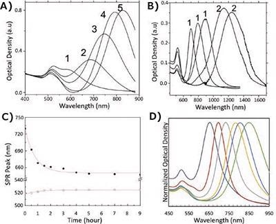
Figure 3. Controlling the aspect ratio of gold nanorods. A) Effect of increasing silver nitrate concentration on the nanorod aspect ratio and resulting optical properties upon synthesis. (1–5) indicate increasing additions of 4 mM AgNO3 from 50–300 μL to identical growth solutions.31 B) The effect of using single (1) and binary (2) surfactant systems in the synthesis of gold nanorods.31 C) The effect of heating on the LSPR peak (closed dots) and TSPR peak (open dots) of aqueous solutions of gold nanorods.42 D) An array of nanorods synthesized using combinations of tuning reactions discussed. Image Credit: Merck Millipore Sigma
Poor Shape Control (4)
Throughout the synthesis of any nanorod, it is inevitable that shape impurities will appear. However, these impurities can be minimized and monitored. Figure 2D shows a nanorod reaction with substandard shape purity. Undesired spheres in the reaction have a strong absorbance at 510–525 nm, leading to an increase in the apparent TSPR peak. Therefore, monitoring the LSPR/TSPR ratio is a significant indicator of overall shape purity.
A 'good' ratio of at least 3.5 signifies ~90% shape purity.59–60 Thus, if a large quantity of impurities is seen, this can mean that reactants are too old, reaction temperature was too high, not enough AgNO3 was used in the reaction, or too high of a BDAC/CTAB ratio was used, highlight a few possible problems.
Post-synthesis separations can be carried out to eliminate undesirable shapes, as will be outlined in the next section. Likewise, multiple variations of the basic cylindrical shape of nanorods can be brought about during their synthesis.
Binary surfactant reactions such as those utilizing both BDAC and CTAB produce rods with sharpened corners, giving them a structure that appears more 'brick-like' (Figure 4A) versus the conventional CTAB reaction (Figure 4B). Spectrally, this can be witnessed as a supplementary small peak slightly red-shifted from the typical TSPR peak (Figure 2A vs 2C).
'Dog bones' or 'dumbbells' are a further property that can drastically affect the spectra of nanorods (Figure 4C). Multiple groups noted these features appearing upon secondary additions of ascorbic acid reporting that they are pH driven.32,50–51 The observation these same features has been recorded here via the addition of excessive ascorbic acid in a single addition. Features like sharp corners and dog bones can be 'softened' through thermal treatment, resulting in a lilted intensity of their additional spectral features and an overall blue-shift of their LSPR.
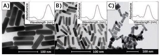
Figure 4. TEMs of gold nanorods demonstrating a correlation between absorbance spectra and anisotropic geometry of gold nanorods. Insets are typical corresponding UV/Vis spectra for the given shape, spanning 400–1,000 nm. A) Gold nanorods synthesized in binary surfactant system containing CTAB and BDAC. B) Gold nanorods synthesized using only CTAB. C) Dog bone- or dumbbell-shaped nanoparticles.40 Image Credit: Merck Millipore Sigma
Insufficient Purification (5)
Subsequent to any synthesis, purification is necessary to eliminate excess reactants and limit the overall concentration of CTAB for storage. Nanorods have a tendency to aggregate if left in the original reactants for 48 hours or more. Therefore, purification is generally achieved by pelleting via centrifugation and the most common drawback is aggregation post-centrifugation.
Since various sizes of particles will demand different spin speeds to drop out of solution as deemed appropriate, optimization of particular nanorods is necessary. Centrifuging particles at speeds that are too fast or for prolonged periods of time can lead to the formation of aggregates, while under-centrifuging results in the losses of nanorods. This is especially true for nanorods with higher aspect ratios with absorbance outside of the visible spectra.
Paradoxically, higher aspect ratio rods have greater stability in solution and, thus, demand increased spin speeds for precipitation. Therefore, it is advised that the UV/Vis spectra of supernatants is checked prior to discarding. It is also crucial to be mindful of the final concentration of CTAB in any solution, as the nanorods may become unstable removal if too much CTAB is removed.
It is generally recommended that >10 mM surfactant through all purification steps is maintained. Particles can then be diluted safely to 1 mM CTAB for final storage. As illustrated Figure 5, centrifugation can also be used for further separation and purification of a sample with high shape impurities. While most of the particles will stay together in a pellet (3), it can be observed that on the fringes a disparity in color (1 and 2) indicates sphere and rod separation.
While the technique is not the most efficient, centrifugal separation can be used to enhance purity and has been previously reported.61 Other groups have also surveyed multiphase centrifugal separations62 and flocculation63 techniques to some degree of success.
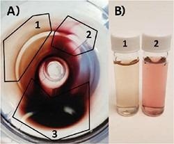
Figure 5. A) Top-down view of centrifuge tube containing gold nanoparticle pellet. Particles partially separate according to size and particle geometry: 1) Very high shape purity nanorod population. 2) Primarily nanosphere population. 3) Mix of both populations. B) Photo of (1) highly purified gold nanorods and (2) primarily spheres from pellet in A). Image Credit: Merck Millipore Sigma
Incomplete Characterization (6)
In order to characterize nanorods correctly, it is crucial to use several complimentary techniques to evaluate their quality. The most frequently used characterization tools are UV/Vis spectrophotometers, dynamic light scattering (DLS), scanning electron microscopy (SEM), transmission electron microscopy (TEM) and zeta potential. As previously outlined, UV/Vis spectroscopy is the optimal tool for measuring shape purity, aspect ratio and rod quality for a group of nanoparticles. However, UV/Vis offers limited information regarding actual size.
TEM and SEM are the most powerful tools for confirming particle dimension, but without taking the appropriate number of images at multiple magnifications, it is easy to unintentionally bias the true average dimension of your particles. Figure 6 exhibits just how various nanorods can look and the variances in quality based on what section of a TEM grid you select for observation.47
Figure 6C shows that particles can have the inclination to 'self-sort' when drying on a grid. Groups of impurities such as spheres or cubes can be segregated from sections of rods leaving the apparition of a high shape purity synthesis.
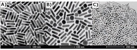
Figure 6. TEM’s of gold nanorods illustrating selection bias. A) Section of TEM grid indicates high purity rod synthesis. B) Different section of same grid shown by (A) indicates a large number of impurities in sample. C) TEM demonstrates shape segregation drying pattern on TEM grid. Image Credit: Merck Millipore Sigma
Methods such as dynamic light scattering (DLS), which are generally utilized for the determination of spherical nanoparticles, depend on algorithms that are have not been developed for detection and sizing of nanorods due to their anisotropic geometry. Yet, measurement of the zeta potential can still work well as an appropriate marker of stability for nanorods stabilized by CTAB. Generally, after purification, stable as-synthesized gold nanorods possess a zeta potential >+30 mV; lower values specify particle instability and a good chance of aggregation with time.
Alternatively, gold nanorods can experience ligand exchanges to be sterically stabilized by neutral moieties, such as polyethylene glycol (PEG). This technique is often utilized to eliminate CTAB and limit particle toxicity, leading to a zeta potential of ±5 mV.
Conclusions
The synthesis of gold nanorods via colloidal seed-mediated growth enables the user tunability over a broad range of aspect ratios and equivalent LSPR optical peaks, with the chance for simple volumetric synthesis scaling. Yet, this tunability has its drawbacks; a synthesis that necessitates accurate control across a range of variables in several phases of the process. The considerable list of variables results in being difficult to sustain consistency of reactions and reproducibility. This has the potential to frustrate researchers who are striving for large-scale in vivo studies.
Because of these complexities, small-scale manufacture can be expensive to maintain.64 Therefore, rather than produce them in-house many researchers opt to purchase nanorods, as many companies now offer them as products with standardized characterization and good quality control.
References and Further Reading
- (1) Lee, K. S.; El-Sayed, M. A. J. Phys. Chem. B 2005, 109 (43), 20331–8.
- Jain, P. K.; Huang, X.; El-Sayed, I. H.; El-Sayed, M. A. Acc. Chem. Res. 2008, 41 (12), 1578–86.
- Loo, C. H.; Lee, M.-H.; Hirsch, L. R.; West, J. L.; Halas, N. J.; Drezek, R. A. Proc. SPIE 2004, 5327, 1–4.
- Huang, X.; El-Sayed, I. H.; Qian, W.; El-Sayed, M. A. Nano Lett. 2007, 7 (6), 1591–1597.
- El-Sayed, I. H.; Huang, X.; El-Sayed, M. A. Cancer Lett. 2006, 239 (1), 129–135.
- Aslan, K.; Leonenko, Z.; Lakowicz, J. R.; Geddes, C. D. J. Fluoresc. 2005, 15 (5), 643–654.
- Aslan, K.; Lakowicz, J. R.; Geddes, C. D. Curr. Opin. Chem. Biol. 2005, 9 (5), 538–544.
- Travis, K.; Aaron, J.; Harrison, N.; Sokolov, K. Plasmonics in Biology and Medicine V, VoDinh, T.; Lakowicz, J. R., Eds. 2008; Vol. 6869, pp H8690–H8690.
- Mubeen, S.; Lee, J.; Lee, W. R.; Singh, N.; Stucky, G. D.; Moskovits, M. ACS Nano 2014, 8 (6), 6066.
- Moran, C. E.; Steele, J. M.; Halas, N. J. Nano Lett. 2004, 4 (8), 1497–1500.
- Maier, S. A.; Brongersma, M. L.; Kik, P. G.; Meltzer, S.; Requicha, A. A. G.; Atwater, H. A. Adv. Mater. 2001, 13 (19), 1501–1505.
- Jackson, J. B.; Halas, N. J. Proc. Natl. Acad. Sci. U.S.A. 2004, 101 (52), 17930–17935.
- Gryczynski, I.; Malicka, J. B.; Gryczynski, Z.; Nowaczyk, K.; Lakowicz, J. R. Proc. SPIE 2004, 5327, 37–44.
- Cole, J. R.; Halas, N. J. Appl. Phys. Lett. 2006, 89 (15).
- Charnay, C.; Lee, A.; Man, S. Q.; Moran, C. E.; Radloff, C.; Bradley, R. K.; Halas, N. J. J. Phys. Chem. B 2003, 107 (30), 7327–7333.
- Xu, X.; Du, Q.; Peng, B.; Xiong, Q.; Hong, L.; Demir, H. V.; Wong, T. K. S.; Ko Kyaw, A. K.; Sun, X. W. Appl. Phys. Lett. 2014, 105 (11), 113306.
- Mackey, M. A.; Ali, M. R. K.; Austin, L. A.; Near, R. D.; El-Sayed, M. A. J. Phys. Chem. B 2014, 118 (5), 1319–1326.
- Dickerson, E. B.; Dreaden, E. C.; Huang, X. H.; El-Sayed, I. H.; Chu, H. H.; Pushpanketh, S.; McDonald, J. F.; El-Sayed, M. A. Cancer Lett. 2008, 269, 57.
- Zhang, L.; Xia, K.; Lu, Z.; Li, G.; Chen, J.; Deng, Y.; Li, S.; Zhou, F.; He, N. Chem. Mater. 2014, 26 (5), 1794.
- Jia, H.; Fang, C.; Zhu, X. M.; Ruan, Q.; Wang, Y. X. J.; Wang, J. Langmuir 2015, 31 (26), 7418.
- Pan, S. L.; Chen, M.; Li, H. L. Colloids Surf., A 2001, 180 (1–2), 55.
- Sun, Y.; Xia, Y. Science 2002, 298 (5601), 2176–2179.
- Mock, J. J.; Oldenburg, S. J.; Smith, D. R.; Schultz, D. A.; Schultz, S. Nano Lett. 2002, 2 (5), 465–469.
- Loweth, C. J.; Caldwell, W. B.; Peng, X.; Alivisatos, A. P.; Schultz, P. G. Angew. Chem. Int. Ed. 1999, 38 (12), 1808–1812.
- Li, Z.; Chung, S.-W.; Nam, J.-M.; Ginger, D. S.; Mirkin, C. A. Angew. Chem. Int. Ed. 2003, 42 (20), 2306–2309.
- Yu, Y. Y.; Chang, S. S.; Lee, C. L.; Wang, C. R. C. J. Phys. Chem. B 1997, 101 (34), 6661.
- Ghoreishi, S. M.; Behpour, M.; Khoobi, A. Anal. Methods 2012, 4, 2475.
- Huang, S.; Ma, H.; Zhang, X.; Yong, F.; Feng, X.; Pan, W.; Wang, X.; Wang, Y.; Chen, S. J. Phys. Chem. B 2005, 109 (42), 19823–19830.
- Alekseeva, A. V.; Bogatyrev, V. A.; Khlebtsov, B. N.; Mel’nikov, A. G.; Dykman, L. A.; Khlebtsov, N. G. Colloid J. 2006, 68 (6), 661–678.
- Zhu, J.; Yong, K. T.; Roy, I.; Hu, R.; Ding, H.; Zhao, L. L.; Swihart, M. T.; He, G. S.; Cui, Y. P.; Prasad, P. N. Nanotechnology 2010, 21 (28).
- Nikoobakht, B.; El-Sayed, M. A. Chem. Mater. 2003, 15 (10), 1957– 1962.
- Chungang, W.; Tingting, W.; Zhanfang, M.; Zhongmin, S. Nanotechnology 2005, 16 (11), 2555.
- Smith, D. K.; Korgel, B. A. Langmuir 2008, 24 (3), 644–649.
- Ye, X.; Zheng, C.; Chen, J.; Gao, Y.; Murray, C. B. Nano Lett. 2013, 13 (2), 765.
- Ye, X.; Gao, Y.; Chen, J.; Reifsnyder, D. C.; Zheng, C.; Murray, C. B. Nano Lett. 2013, 13 (5), 2163.
- Koeppl, S.; Ghielmetti, N.; Caseri, W.; Spolenak, R. J. Nanopart. Res. 2013, 15 (3), 1471.
- Johnson, C. J.; Murphy, C. J.; Dujardin, E.; Davis, S. A.; Mann, S. J. Mater. Chem. 2002, 12 (6), 1765.
- Burrows, N. D.; Harvey, S.; Idesis, F. A.; Murphy, C. J. Langmuir 2016.
- Murphy, C. J.; Sau, T. K.; Gole, A. M.; Orendorff, C. J.; Gao, J.; Gou, L.; Hunyadi, S. E.; Li, T. J. Phys. Chem. B 2005, 109 (29), 13857–70.
- Alex, S. A.; Satija, J.; Khan, M. A.; Bhalerao, G. M.; Chakravarty, S.; Kasilingam, B.; Sivakumar, A.; Chandrasekaran, N.; Mukherjee, A. Anal. Methods 2015, 7 (13), 5583–5592.
- Murphy, C. J.; Thompson, L. B.; Chernak, D. J.; Yang, J. A.; Sivapalan, S. T.; Boulos, S. P.; Huang, J.; Alkilany, A. M.; Sisco, P. N. Curr. Opin. Colloid Interface Sci. 2011, 16 (2), 128.
- Zou, R.; Zhang, Q.; Zhao, Q.; Peng, F.; Wang, H.; Yu, H.; Yang, J. Colloids Surf., A 2010, 372, 5.
- Jana, N. R. Small 2005, 1 (8–9), 875.
- Vigderman, L.; Zubarev, E. R. Chem. Mater. 2013, 25 (8), 1450.
- Perez-Juste, J.; Pastoriza-Santos, I.; Liz-Marzan, L. M.; Mulvaney, P. Coord. Chem. Rev. 2005, 249 (17–18), 1870–1901.
- Ye, X.; Jin, L.; Caglayan, H.; Chen, J.; Xing, G.; Zheng, C.; Doan- Nguyen, V.; Kang, Y.; Engheta, N.; Kagan, C. R.; Murray, C. B. ACS Nano 2012, 6 (3), 2804.
- Scarabelli, L.; Sanchez-Iglesias, A.; Perez-Juste, J.; Liz-Marzan, L. M. J. Phys. Chem. Lett. 2015, 6 (21), 4270.
- Scarabelli, L.; Grzelczak, M.; Liz-Marzan, L. M. Chem. Mater. 2013, 25 (21), 4232.
- Jana, N. R.; Gearheart, L. A.; Murphy, C. J. J. Phys. Chem. B 2001, 105 (19), 4065.
- Ratto, F.; Matteini, P.; Rossi, F.; Pini, R. J. Nanopart. Res. 2010, 12 (6), 2029–2036.
- Gou, L.; Murphy, C. J. Chem. Mater. 2005, 17 (14), 3668–3672.
- Jana, N. R.; Gearheart, L.; Murphy, C. J. J. Phys. Chem. B 2001, 105, 4065–4067.
- Lohse, S. E.; Murphy, C. J. Chem. Mater. 2013, 25 (8), 1250.
- Wang, H.; Wu, Y.; Lassiter, B.; Nehl, C. L.; Hafner, J. H.; Nordlander, P.; Halas, N. J. Proc. Natl. Acad. Sci. U.S.A. 2006, 103 (29), 10856–10860.
- Low, A.; Bansal, V. Biomed. Imag. Interv. J. 2010, 6 (1), e9.
- Meena, S. K.; Celiksoy, S.; Schafer, P.; Henkel, A.; Sonnichsen, C.; Sulpizi, M. Phys. Chem. Chem. Phys. 2016, 18 (19), 13246–13254.
- Chen, H. M.; Peng, H.-C.; Liu, R.-S.; Asakura, K.; Lee, C.-L.; Lee, J.- F.; Hu, S.-F. J. Phys. Chem. B 2005, 109 (42), 19553–19555.
- Perez-Juste, J.; Correa-Duarte, M. A.; Liz-Marzan, L. M. Appl. Surf. Sci. 2004, 226 (1–3), 137–143.
- Link, S.; Mohamed, M. B.; El-Sayed, M. A. J. Phys. Chem. B 1999, 103 (16), 3073.
- Huang, X.; Neretina, S.; El-Sayed, M. A. Adv. Mater. 2009, 21 (48), 4880–4910.
- Sharma, V.; Park, K.; Srinivasarao, M. Proc. Natl. Acad. Sci. U.S.A. 2009, 106 (13), 4981–4985.
- Akbulut, O.; Mace, C. R.; Martinez, R. V.; Kumar, A. A.; Nie, Z.; Patton, M. R.; Whitesides, G. M. Nano Lett. 2012, 12 (8), 4060–4064.
- Park, K.; Koerner, H.; Vaia, R. A. Nano Lett. 2010, 10 (4), 1433–1439.
- NanoHybrids Make or Buy Gold Nanoparticles: A Quick Economic Analysis.

This information has been sourced, reviewed and adapted from materials provided by Merck.
For more information on this source, please visit Merck.