Lubricated mechanical conditions are ones in which lubricant is used primarily to reduce the wear and friction of sliding contacts; most mechanical components function under this kind of condition.
The performance and behavior of the lubricant can be impacted by the variation of interfacial friction in a wide range of operating conditions. A more appropriate selection of component materials and lubricants for different applications can be made when machinery and lubricant manufacturers better understand the oil-surface interaction.
This article will specifically explore why the use of Bruker’s liquid heating chamber is advantageous when combined with the block-on-ring tribosystem on the UMT TriboLab™.
TriboLab features options for modularity, meaning it is capable of simulating a wide range of field conditions, allowing better evaluation of the wear and friction characteristics of lubricants and materials in application engineering, quality control and research and development.
Why a Liquid Heating Chamber
Productivity in lubrication is enhanced by adding a liquid heating chamber to the tribosystem portfolio. The fully enclosed liquid heating chamber from Buker is specially designed to prevent liquid spillage even during high speed horizontal axis rotation (≤5000 rpm) and stores up to 170 mL.
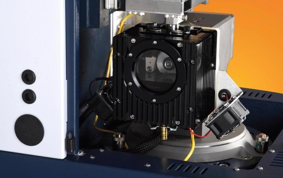
Figure 1. UMT TriboLab Liquid Heating Chamber on Block-On-Ring Module. Image Credit: Bruker Nano Surfaces
Figure 2a shows the chamber on the TriboLab Block-On-Ring Module. The module promotes environmental sustainability by reducing chemical wastage through the use of only a small amount of lubricant to continuously supply sufficient lubrication for materials testing.
The chamber has direct-contact heat transfer between the heater and liquid, enabling elevated temperature testing. The heat transfer is done from ambient to 150°C, as shown in Figure 2b, and uses rapid and homogenous heating to the entire lubricant reservoir.
Real-world work conditions in lubrication and material testing can be easily simulated by programming the desired test sequences, ramp rates and temperature setpoints.
It is possible to configure the block-on-ring system to enable an unprecedented breadth of wear testing when it is used in conjunction with the TriboLab “Gold Series” linear-force sensors (1 mN to 2 kN load range).
Real-time data acquisition and monitoring of the test specimen dimensional change can be easily used to calculate the rate of wear and/or total wear.
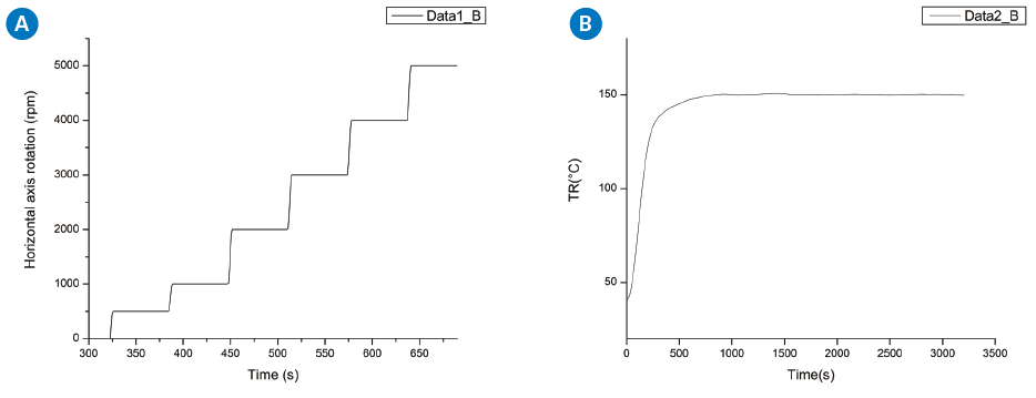
Figure 2. (a) High speed horizontal axis rotation up to 5000 rpm; (b) Rapid and homogenous heating from ambient to 150°C. Image Credit: Bruker Nano Surfaces
Characterization of Lubricity by Stribeck Test
The relationship between friction and the Hersey number (ηV/Fz), also known as the Stribeck curve, is typically used to investigate the overview spectrum of lubrication transition from boundary to hydrodynamic.
Through the use of the Stribeck curve, it is possible to show how friction in fluid-lubricated contacts behaves non-linearly of contact load, entrainment velocity and lubricant viscosity.
A fluid that can be drawn into a converging gap is needed to generate a Stribeck curve; this creates pressure to support the load, as seen in Figure 3.
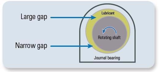
Figure 3. Converging gap of a journal bearing. Image Credit: Bruker Nano Surfaces
However, without a proper tribotester, it is challenging to develop the needed velocity to build up the film thickness and pressure needed to achieve the hydrodynamic lubrication regime. The tests are made more convenient and simpler through the use of Bruker’s liquid heating chamber for block-on-ring testing.
The liquid heating chamber on a TriboLab equipped with a block-on-ring drive was used to demonstrate the Stribeck curve method for characterizing the lubricity of synthetic and bio-based lubricants at different temperatures.
For these experiments, an SAE 52100 steel block was pressed against a 35 mm diameter chrome steel ring submerged in 130 mL of lubricant. The study used two commercially available lubricants: Synthetic-B, which was fully synthetic, and Bio-A, which was bio-based.
A maximum load of up to 20 N was applied on the chrome steel ring while it was revolved at a horizontal axis up to a maximum rotating speed of 5000 rpm.
Precise temperature control from direct heating the lubricant at three different temperatures (25°C, 80°C and 120°C) was utilized to study the friction behavior of the lubricants over a wide range of temperatures.
Coefficient of Friction and Lubrication Regimes
Lubricant film thickness and asperity height influence the frictional characteristics of metal to metal during lubricated sliding contacts.
By using a proper tribosystem setup, it is easy to distinguish the full fluid-film separation (hydrodynamic), semi fluid-film separation, and the contact interface going through the region of asperity contact (boundary) by plotting the coefficient of friction (COF) against the V/Fz ratio. This is shown in Figure 4.
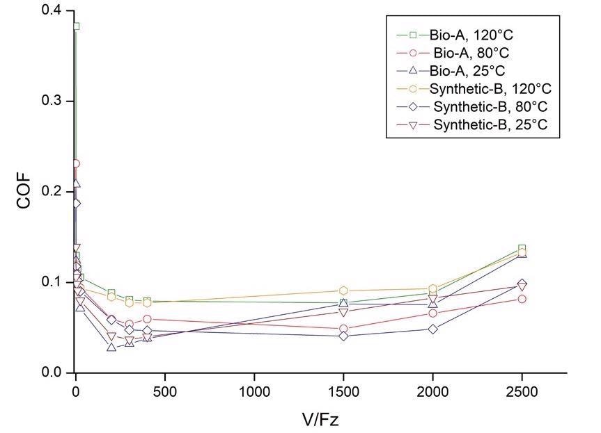
Figure 4. Stribeck curves generated under different temperatures. Image Credit: Bruker Nano Surfaces
As the two metal surfaces come into direct contact and the load is primarily supported via surface asperities, high friction (COF>0.1) was observed at low V/Fz.
As the lubricants transited from the boundary to the mixed lubrication regime, where both asperities and lubricant film support the load, the average COF value decreased (in the range of 0.05-0.1).
Asperity contact was negligible at higher V/FZ, where the friction coefficient is relatively lower; hydrodynamic pressure exerted by the lubricant mainly supports the load in this case.
At this regime, the coefficient of friction is minimal (COF<0.08). However, the increased coefficient of friction observed toward V/Fz >2000 suggests that the
lubrication film may be broken, thus bringing the lubrication back to the mixed regime with asperity contacts.
To determine the performance of lubricants, the relationship between the friction coefficient and temperature at the contact surface is important. This is especially important in boundary-friction-dominated operating conditions, where the viscosity of a lubricant changes with temperature.
The contact temperature increased from 25°C to 120°C by the friction coefficients of Synthetic-B and Bio-A lubricants. Usually, the lower temperature range has a less rapid rise in friction coefficient.
Because of higher viscosity, the lubrication film is thicker at lower temperatures. The two lubricants had very similar performances, so understanding their minor differences made it possible to identify Bio-A as a greener substitute for sustainability and green tribology.
Lubricated Sliding Wear Test
A common way of assessing the wear behavior of materials in laboratories is with the block-on-ring wear test. This is because it is feasible in scientific investigations of wear mechanisms in various conditions.
The ASTM G77-17 standard using block-on-ring wear tests to report COF, scar volume, scar depth and scar width in the ranking of resistance of materials to sliding wear.
The scar depth of test blocks at various temperatures is shown in Figure 5. The TriboLab provides a better understanding of the mechanisms of wear formation during sliding wear tests by providing real-time monitoring of COF and in-situ scar depth measurements.
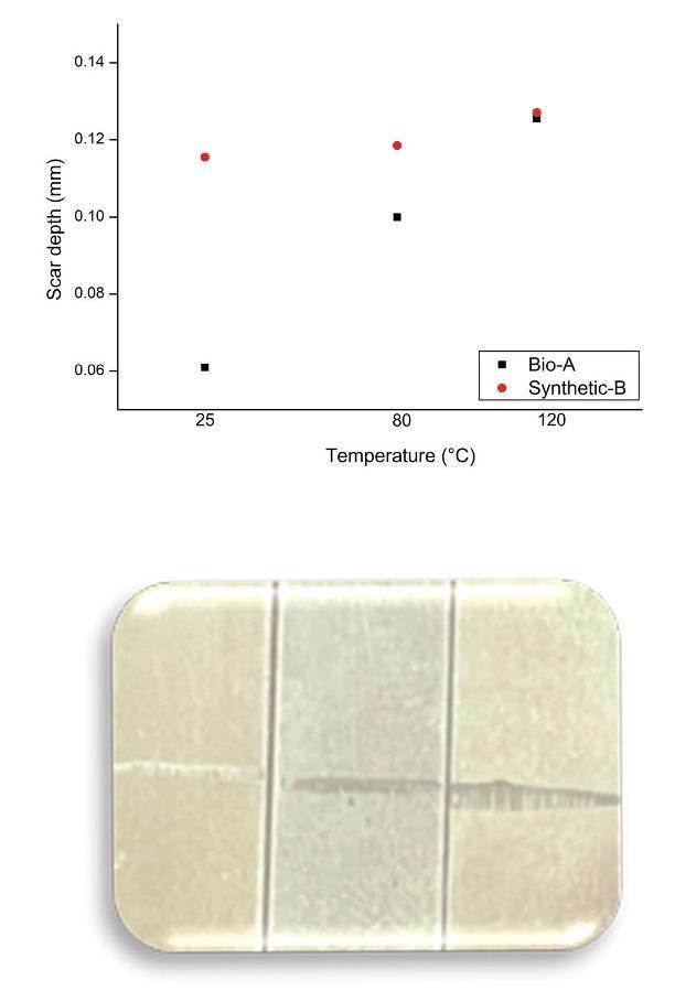
Figure 5. Measured scar depth of test blocks at 25°C, 80°C and 120°C, respectively. Image Credit: Bruker Nano Surfaces
The average friction coefficient of the Synthetic-B and Bio-A lubricants used in the study and the block scar volume is shown in Figure 6. The width of the scar was used to calculate the block scar volume.
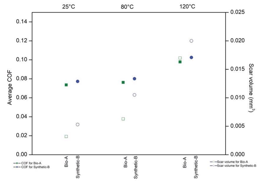
Figure 6. Average COF and calculate block scar volume at 25 °C, 80 °C and 120 °C, respectively. Image Credit: Bruker Nano Surfaces
Plotting these two parameters within the same graph can be used to easily assess and compare the lubricant performance. The study found that across the tested temperatures, Synthetic-B and Bio-A lubricants were very close in performance. This finding is in agreement with the Stribeck curve described above.
Conclusions
A reliable method for lubricant evaluation has been shown to be the Stribeck curve generation that is done using unidirectional testing. This is because of its clearer discrimination of hydrodynamic, mixed and boundary lubrication regimes.
Unprecedented flexibility is provided by the benchtop UMT TriboLab with block-on-ring module and liquid heating chamber by allowing researchers to perform multiple measurements at different conditions, an essential part of understanding key performance differences of lubricants at different regimes.
The TriboLab has a modular design that allows for materials and lubricant testing at a horizontal axis rotation, ideal for a wide range of test methods including ASTM D3704, ASTM D2782, ASTM D2714, ASTM D2509, ASTM G77, among other testing standards.
References
- Earle, J. and S. Kuiry, "Characterization of Lubricants for Research and Development, Quality Control and Application Engineering," Bruker Application Note #1000 (2012).
- Shaffer, S., "Generating a Stribeck Curve in a Reciprocating Test (HFRR/SRV-type test)," Bruker Application Note #1004 (2014).
- ASTM G77-17, Standard Test Method for Ranking Resistance of Materials to Sliding Wear Using Block-on-Ring Wear Test, ASTM International, West Conshohocken, PA, (2017).

This information has been sourced, reviewed and adapted from materials provided by Bruker Nano Surfaces.
For more information on this source, please visit Bruker Nano Surfaces.