Carbon fiber reinforced plastic (CFRP) is a composite material produced by strengthening a thermosetting resin with carbon fibers.
CFRP is stronger, lighter and more rigid than steel, and while it is relatively expensive compared to traditional metal and resin materials, its excellent mechanical properties are leading to increased use in industrial applications, particularly in the automotive field.
Carbon fiber reinforced thermoplastic (CFRTP) has been developed in recent years, enhancing the productivity, processability, and recyclability of CFRP.
Because CFRTP can be molded much more rapidly than CFRP, it is more suited to applications requiring mass production. As expected, this has seen considerable uptake in the automotive industry.
While both CFRP and CFRTP offer superior mechanical properties to traditional resin materials, the potential for internal voids and cracks occurring throughout the manufacturing process remains present.
These voids and cracks will likely lead to defects in the end product. The mechanical properties of both CFRP and CFRTP are also controlled by the orientation of the carbon fibers present in the materials.
If the quality of CFRP and CFRTP products is to be kept consistently high, an investigation should be undertaken into whether voids and cracks are present in the resin and whether the orientation of the fibers is correct.
These investigations can be conducted using X-ray CT systems, with these systems allowing non-destructive observation of the three-dimensional structure of the investigation target.
This article details observations of voids and the fiber orientation in CFRTP using the Shimadzu inspeXio SMX-225CT FPD HR Plus microfocus X-ray CT system (Figure 1).
Figure 1. inspeXio™ SMX™-225CT FPD HR Plus Microfocus X-ray CT System. Image Credit: Shimadzu Scientific Instruments
Observation of CFRTP
Figure 2 displays the CFRTP sample’s external appearance. This sample was scanned as part of this experiment and is comprised of a multi-layered laminated material with overall dimensions of 30 mm × 3 mm × 1 mm.
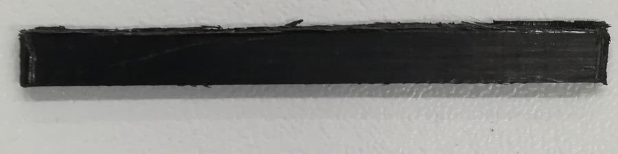
Figure 2. External Appearance of CFRTP Sample. Image Credit: Shimadzu Scientific Instruments
Figure 3 displays an MPR (Multi Planar Reconstruction) screen. Here, cross-sections viewed from various angles are displayed on the same screen after a section of the sample has been scanned by the CT system.
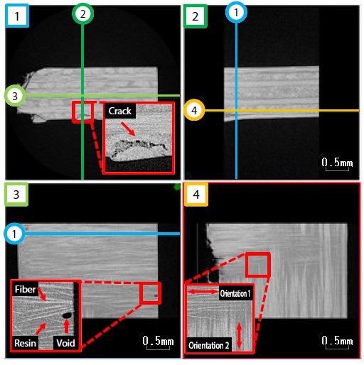
Figure 3. MPR Screen Showing Cross-Sectional Images of CFRTP. Image Credit: Shimadzu Scientific Instruments
Locations of each cross-section in the sample can be identified via the numbers in the upper left of each screen and the lines drawn in the screens.
Higher density areas in the cross-sectional images are shown as whiter as density increases, while lower density areas are shown as blacker. This approach enables cracks, voids, resin, and carbon fibers to be visually identified.
Observing the various sections confirms that the structure of the CFRTP is comprised of densely arranged carbon fibers with a width of several μm. These fibers form layers oriented in a specific direction in the composite material, while the fibers’ orientations are orthogonal in each layer.
Figure 4 shows CT data displayed on screens. These screens show three-dimensional representations of the scanned sample, allowing easier understanding of its structure.
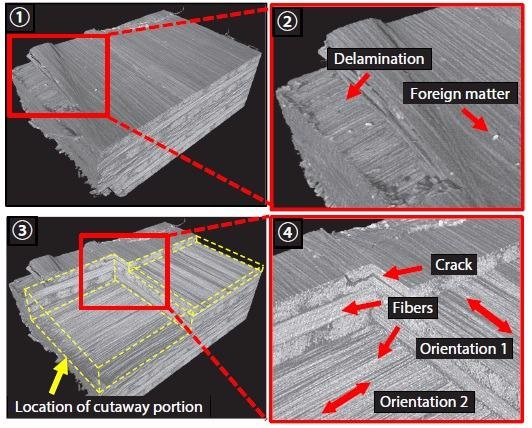
Figure 4. Screens Showing 3D Representations of CFRTP. Image Credit: Shimadzu Scientific Instruments
Screen 1 is the result of observation close to the sample’s surface, while Screen 2 is an enlarged view of Screen 1. Screen 2 shows a particulate piece of foreign matter with a higher density than the fibers and delamination at the sample surface. This is believed to have occurred because force was applied.
Screen 3 displays the interior of the sample as observed by cutting away a section of the sample surface in the CT data, while Screen 4 is an enlarged view of Screen 3. The laminated structure shown here is formed by the orthogonally-arranged layers of carbon fibers and it is possible to observe a crack close to the surface.
In the screen shown in Figure 5, voids detected in the sample interior have been colored according to their volumes. It is possible to select detection targets based on information such as the XYZ coordinates, void volume, and diameter, and this enables the extraction of voids that specifically impact the overall product quality.
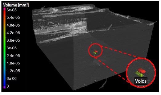
Figure 5. Screen Showing 3D Representation of CFRTP: Void Analysis. Image Credit: Shimadzu Scientific Instruments
Figure 6 displays a screen showing the result of an analysis of fiber orientation. Here, standard orientation is defined as 0° in the data, while fibers in the CFRTP have been colored according to their deviation angles.
The histogram displayed in Figure 7 illustrates the analysis results from Figure 6 in graph form. In this graph, the x-axis represents the deviation angle with regards to the standard orientation of the fibers, while the y-axis shows the frequency of each deviation angle.
Here, the frequency can be understood to be the percentage of pixels of each deviation angle, whereby the total number of pixels in the CFRTP image is 100%.
Illustrating deviation as colors and numbers (Figure 6 and Figure 7) allows the condition of fiber orientation to be easily understood. The results presented here confirm that a significant number of the fibers are oriented at 90° to the standard orientation.
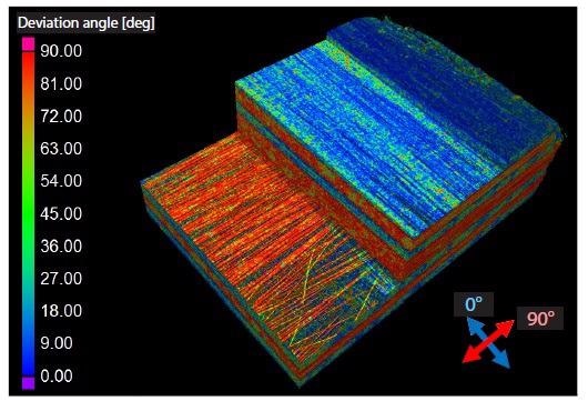
Figure 6. Screen Showing 3D Representation of CFRTP: Fiber Orientation Analysis. Image Credit: Shimadzu Scientific Instruments
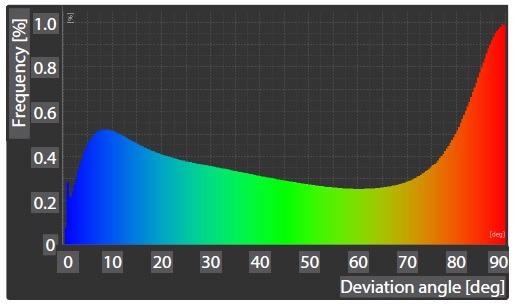
Figure 7. Histogram Showing Fiber Orientation Angles of CFRTP. Image Credit: Shimadzu Scientific Instruments
Conclusion
This experiment demonstrates that the inspeXio SMX-225CT FPD HR Plus microfocus X-ray CT system is capable of analyzing the size and location of voids contained in CFRP and CFRTP, as well as the orientation of the carbon fibers in the resin matrix.
This system is highly suited for the development and quality control of products using fiber composite materials.
Acknowledgments
Produced from materials originally authored by T. Hashimoto from Shimadzu Corporation.

This information has been sourced, reviewed and adapted from materials provided by Shimadzu Scientific Instruments.
For more information on this source, please visit Shimadzu Scientific Instruments.