An electronic test equipment manufacturer experienced consistency concerns with its waveform analyzer, likely due to overheating mechanisms on a printed circuit board (PCB) inside the chassis.
Comprehensive research was performed on all electronic parts on the suspect board to determine their maximum operating temperatures. The board was then put on a test stand and ran to mimic the environment during processor-intensive operation.
Fundamental elements were evaluated with a contact thermometer to verify if any were running above their maximum temperatures. All sat within their required limits, but some ran close to their maximum temperatures.
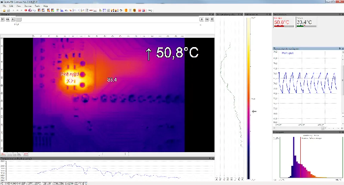
Image Credit: Optris GmbH & Co. KG
The problem with employing thermocouples, such as surface-mount devices (SMD), for temperature measurement on minute structures is that they must precisely reflect the electronics' actual temperature.
The thermal mass for small PCB parts is minimal. In comparison, a thermocouple has sufficient thermal capacity to affect the component’s temperature during testing.
The thermocouple and its wiring absorb heat from the electronics component, generating lower temperature readings than the true temperature of the SMD part without the thermocouple. This incites smaller temperature amplitude measurements under stable conditions and incorrect thermal dynamics analyses.
Temperature testing inside the equipment chassis is essential to demonstrate the influence of internal temperatures in an enclosed casing on component temperatures.
Remote temperature measurements are more difficult because of possible line-of-sight obstructions due to the equipment enclosure.
Improving Temperature Measurement in Electronic Enclosures Using Infrared
The thermographic assessment of electronic parts and assemblies is a well-established testing method for identifying failures and ensuring quality control, from creating early prototypes to mass production.
This approach identifies numerous concerns, including hotspots and unusual temperature scatterings on the surface of PCBs, integrated circuits, and multichip modules.
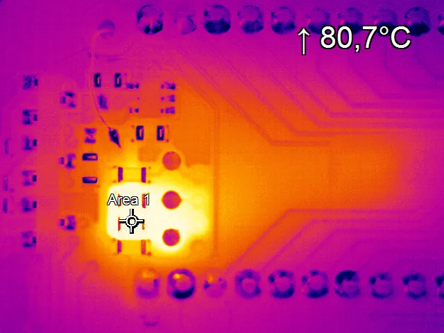
Image Credit: Optris GmbH & Co. KG
It can detect heightened irregular contact resistances, hidden joint fractures, power losses caused by radio frequency mismatch, inaccurate thermal connections of heat sinks, short circuits, and soldering flaws like cold solder joints.
An infrared camera with infrared-transmissive materials was used in this process to precisely measure the temperatures of all critical board components while imitating standard operating conditions inside the equipment casing (chassis).
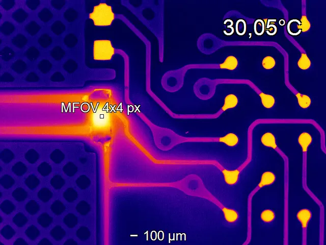
Image Credit: Optris GmbH & Co. KG
A top cover segment was removed and examined with various infrared transmissive materials, starting with Saran wrap, which is highly transmissive in the infrared area, offsetting less than 10 % of the signal while still fluttering when the instrument fan is engaged; its stability creates some issues.
Zinc Selenide (ZnSe) is deemed the ideal solution because of its robustness and observation capabilities, but a window big enough to cover the whole PC board is excessively expensive. Calcium Fluoride infrared windows, typically utilized for electrical switchgear infrared testing, are the optimum solution.
Although their infrared transmission is less than ZnSe, this can be justified when generating precise measurements. The infrared windows’ metal frames make them simple to install into the metal casing, and their cost-effectiveness enables several windows to collect information on all fundamental elements.
Two devices were quickly revealed to be running above temperature because of their mounting positions near other heat-producing devices and insufficient airflow to diffuse the accumulated heat.
Infrared Camera vs. Thermocouple for Measuring Thermal Electronic Components
The Optris Xi 400 is compact and easily fits to a rail system above and below the equipment chassis where infrared windows are positioned. It is angled to enhance the line of sight to the key mechanisms.
PIX Connect software makes it simple to establish spots or small regions to assess the hottest pixel within the enclosed spaces, with no restrictions on how many components can be tracked.
Time vs. temperature data can be easily gathered and kept in CSV files for further research and examination. The software’s “Hot Spot” tool is beneficial for detecting the board’s hottest area.
Optris: A Guide to IR Microscope Optics for Electronics
Video Credit: Optris GmbH & Co. KG
Accurately measuring infrared transmission through the windows is essential, and the PIX Connect transmissivity setting enables simple transmission analysis by comparing a target’s temperature without a window to that with the infrared window, altering the transmission factor until both temperatures align.
It was also observed that putting a contact thermocouple on a small device can decrease the tool’s temperature by drawing heat away, generating more accurate measurements from the infrared camera than those made with a thermocouple.
Measurements on ceramic and all polymer-based materials are precise, but carbon black must be used on metal cans to enhance surface emissivity.

This information has been sourced, reviewed and adapted from materials provided by Optris GmbH & Co. KG.
For more information on this source, please visit Optris GmbH & Co. KG.