This article describes how the advanced LaserNet Fines (LNF) Q200 instrument in the lab offers an economical, precise alternative to conventional methods of analyzing oil debris particles.
LNF offers a “one-stop shopping solution” to determining the type, rate of production, and severity of mechanical faults by measuring the size, distribution, rate of production, and shape features (“silhouettes”) of wear debris in lubricating oil. This article focuses on providing details on how the LNF operates and how its method of particle counting and optical image analysis compares to laser style particle counters and traditional analytical ferrography.
Finally, there are two case studies, one for an Engine Test Cell and one for a Gearbox Accelerated Failure test to demonstrate how LNF technology offers unique, active machine wear results, without the qualitative subjectivity and potential cost of traditional ferrographic analysis.
Overview of LNF Technology
LNF is a particle shape classifier jointly developed by the Naval Research Laboratory and Lockheed Martin with the Office of Naval Research, that also provides a highly accurate particle count for particles greater than 4µm using laser imaging techniques and advanced image processing software.
Silhouette images of all particles larger than 20µm in their major dimension are classified automatically into the following categories:
- Cutting
- Severe sliding
- Fatigue
- Nonmetallic
- Fibers
- Water droplets
These particles are counted by the instrument and a quantitative measure of active machine wear is provided. Bitmap images are then saved and can printed on request for review. Reliability engineers can make more informed decisions using LNF data, by trending both the total particle size distribution and the sub category particles.
Figure 1 shows the basic operating principle of LNF. This involves the following:
- A representative oil sample is drawn from the lubricating system and brought to the unit.
- The oil is drawn through a patented viewing cell that is back-illuminated with a pulsed laser diode to freeze the particle motion.
- The coherent light is transmitted through the fluid and imaged onto an electronic camera.
- Each resulting image is analyzed for particles.
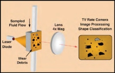
Figure 1. LaserNet Fines® Operating Principle
In either fluid, shape characteristics are determined for particles more than 20µm, and the particle is classified into either a wear category or contaminant category. Classification is achieved using an artificial neural network developed specifically for the LNF system.
Shape features were chosen to provide optimal distinction between the assigned classes of fatigue, cutting, severe sliding, non-metallic particles, fibers, water bubbles, and air bubbles as shown in Figure 2.
The artificial neural network was build up using an extensive library of particles identified by human experts.
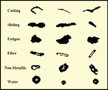
Figure 2. Examples of Particle Class Morphology
LNF Compared to Optical Particle Counters
LNF perform essentially the same function as traditional laser particle counters and analytical ferrography. However, LNF makes use of a two-dimensional sensing array (640X480 pixels) while particle counters use only a one-dimensional array. LNF can examine higher particle concentrations with this added spatial diversity, without special sample preparation, and can also extract particle morphology.
With the ability to recognize shape, the particle counts of LNF are not contaminated by the presence of air bubbles or free water. Instead both those items are subtracted from the debris counts, with the free water fraction identified separately.
LNF does not need calibration with a standard reference material, since the measurement accuracy is intrinsic to its configuration. Its particle size measurements depend on the pixel size of the camera and the magnification power of the optics, both of which are fixed elements which remain virtually unchanged over time. Figure 3 below compares the Particle Counter with LNF with respect to various analysis factors.

Figure 3. LNF Compared to Laser Style Particle Counters
LNF and Traditional Ferrography
For a long time now, ferrography has been a standard method for determining the kind of wear mechanisms and severity of faults found in lubricated machinery. Key drawbacks of traditional ferrography are:
- The test is time-consuming. Due to this, ferrography is done on a case to case basis
- A trained analyst is needed to achieve meaningful results
- The ultimate result is strictly qualitative
LNF, however, counts and classifies all particles in its viewing cell to provide quantitative, repeatable measurements useful for trending and the early assessment of a machines condition. Figure 4 compares analytical ferrography with LNF-based on a number of analysis factors.

Figure 4. LNF Compared to Analytical Ferrography
Case Studies
The capabilities of LNF are further demonstrated in these two case studies:
Case 1: Engine Test Cell
A used oil sample is retrieved from an engine during its break-in period in this example and the synergy between LNF and other techniques such as spectrometric wear metal analysis and analytical ferrography are shown in this example.
LNF results clearly depict the typical and expected high levels of large wear particles during break-in. The large number of particles less than 15µm in size is shown in the bar graph of the wear summary screen in Figure 5. The number of particles more than 20µm is shown in the cutting, severe sliding, fatigue and nonmetallic wear categories.
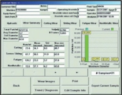
Figure 5. Wear Summary Screen
Figure 6 shows an LNF image map of particle silhouettes for this sample. Most of the particles are identified by LNF and quantified in the wear summary as severe sliding and fatigue particles.
This fact is confirmed by conventional analytical ferrography, shown in Figure 7. Spectrometric oil analysis of this sample also shows a high level of wear metals including aluminum, copper and silicon.
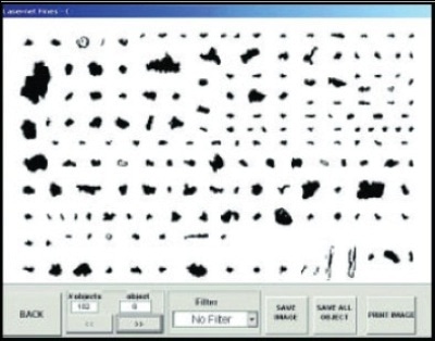
Figure 6. Image Map for Engine Test Cell Sample
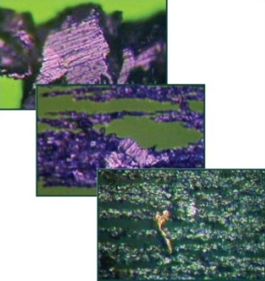
Figure 7. Ferrograms Showing Severe Sliding Wear and Copper Particle during Break-in
Case 2: Gearbox Accelerated Failure Test
Under the ONR CBM program, accelerated gearbox failure tests were conducted at Pennsylvania State University on their Mechanical Diagnostic Test Bed (MDTB) Facility under the ONR CBM program.
These tests were conducted on single-reduction 10hp gearboxes. The gearboxes were run-in for approximately four days at maximum normal load provided by an electric generator on the output shaft. A 3X over torque was applied after that and the system then ran to failure. Every 2h the system was stopped for bore site inspection and oil sampling.
The total particle concentration in the 5-15µm size range shows a general decrease during the run, which was due to gradual removal of debris generated during the run-in period as samples were drawn and replaced with clean fluid. However, an increasing concentration of fatigue particles are seen in several of the size ranges after the 3X over torque was applied.
Conclusion
LNF is a unique analytical instrument and method that combines automatic particle shape classification and particle counting, two essential functions of used oil particle analysis. As shown in the case studies, by combining these two features, early signs of potential problems can be detected through increases in overall particle concentrations, and at the same time, the possible root cause of the problem can be diagnosed from shape classifications.
The LaserNet Fines® Q200 instrument offers a dynamic solution to your detailed oil analysis needs while providing substantial cost-benefits compared to Optical Particle Counters and traditional ferrography techniques.

This information has been sourced, reviewed and adapted from materials provided by AMETEK Spectro Scientific.
For more information on this source, please visit AMETEK Spectro Scientific.