Graphite is a soft, slippery, greyish-black material that has a metallic luster. It is opaque to light and is a good conductor of electricity and heat. Most of the time, graphite is just referred to as carbon. Under vacuum or inert gas, graphite is very temperature-resistant which makes it a potential material for high temperature applications.
By heating graphite up to 3000 °C, its properties are enhanced. Consequently, heat treatment of graphite is an emerging market and graphite has become a vital material for numerous applications worldwide. Graphite is regularly used as a part of composite materials.
In the automotive sector, for instance, graphite is used for manufacturing brakes, clutch facings, mechanical seals, brake linings, friction components, engine parts and also as a substitute for aluminum or steel in car frames.
The newest most remarkable field of application is the lithium-ion batteries of small electronic devices, laptops, tools and electrical cars. Another area is the manufacture of alkaline batteries.
Less known by end users, however crucial to heavy duty industrial applications, is the use as an additive in anti-corrosive paint or the manufacturing of diamond tools/special ceramics.
A more “glamorous” application is the conversion of purified graphite into artificial diamonds. A dirtier yet industrially more significant area of application is the use as roughing electrodes for aluminum production.
Rare but very prominent applications are in carbon brake disks in Formula One racing cars, or as part of reinforced carbon which is used for wing leading edges and the nose cone of the Space Shuttle orbiter to resist huge temperatures during re-entrance into the earth’s atmosphere.
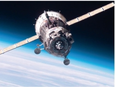
Figure 1. Graphite / Carbon in High-Tech Applications.
Heat Treatment and the Change of Material Properties
Graphitization can be defined as the structural change from highly disordered or defective carbon atom structures towards a perfect 3D crystal of pure graphite. Preferably, graphite is arranged in layers, each of these layers is a separate supra-molecule called graphene (refer Figure 2).
The ordering process is started by heat treatment up to 3000 °C in inert atmosphere. The original carbon material contains multiple small domains of graphene molecules known as basic structural units (BSU). During heat treatment those small domains grow, all differences in orientation of the layers are removed and large straight layers are developed, as shown in Figures 3 and 4.
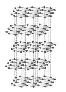
Figure 2. Cut out of carbon atom layers (aka graphene) in graphite.
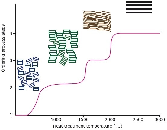
Figure 3. Representation of the graphitization process and of ordering the BSU (basic structural units) of the graphite with increasing temperature.
After carbonization, the carbon atoms are in chaotic order and thus do not have suitable properties. Raising the temperature allows the atoms to travel to more suitable positions as illustrated in Figure 3 and ultimately, at extremely high temperatures, to form ideal graphite with superior properties. The absolute temperatures for graphitization are questionable.
The early stage of graphitization occurs between 1900 °C and 2000 °C and results in interlayer distances > 3.42 Å, as seen in Figure 4. After full straightening, the layer distances are additionally reduced.
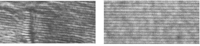
Figure 4. Electron microscope pictures: left graphite layers before heat treatment with disordered layers and right after heat treatment up to 2200 °C with completely straightened layers
After final heat treatment in a Carbolite furnace at up to 3000 °C, the graphite properties are nearly ideal, as well as homogeneous and very reproducible making it an ideal starting material for a number of industrial applications (see above).
Heating Methods on the Way to Graphitization at up to 3000 °C
There are two basic methods for graphitization in Carbolite furnaces. Either the starting material already consists solely of carbon atoms and is very clean with negligible impurities. In this case a graphite furnace of the LHTG range or the HTK range up to 3000 °C is suitable.
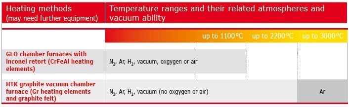
Figure 5. Overview of Carbolite furnaces suitable for carbonization and graphitization.
However, if the starting material contains organic matter of unidentified composition or has a large amount of impurities, it is advised to pre-carbonize the sample in a low temperature hot wall furnace of the GLO range up to 1100 °C to purify the sample under inert gas atmosphere until it is suitable to be heat treated in a more sensitive high temperature graphite furnace (Figure 6 and 7).
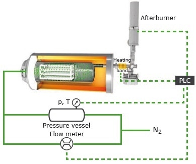
Figure 6. Side view of a schematic drawing of a GLO hot wall furnace equipped with an afterburner for debinding and pyrolysis up to 1100 °C.
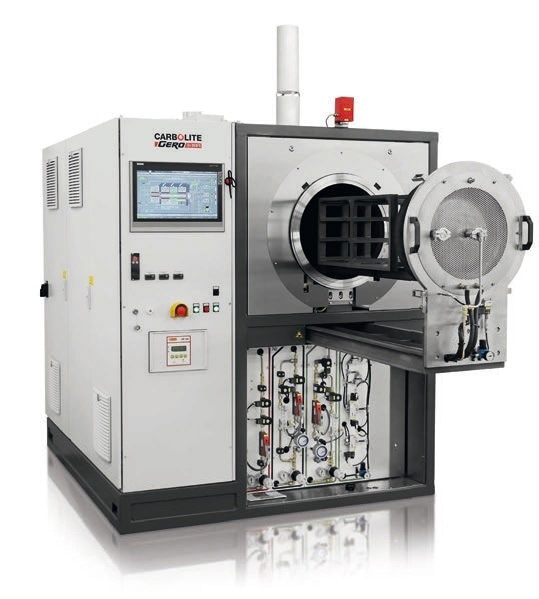
Figure 7. GLO 120/11 Furnace with debinding and pyrolysis equipment.
After purification in a GLO furnace at 1100 °C max., the sample can be transferred into a graphite furnace for final graphitization at up to 3000 °C. For samples with only minor impurities and low contamination of non-carbon atoms, Carbolite offers dedicated cold wall HTK graphite furnaces with specialized debinding equipment, where carbonization and graphitization are performed in one heat treatment step. Those furnaces are fitted with a retort and an intelligent gas guidance system which guarantees that the impurities are securely discharged from the furnace into the afterburner.
During the primary step of heat treatment by slowly ramping up to 800 °C, the inert gas enters the retort via small holes. Once inside, the only way out of the furnace is through the main gas outlet which is located directly within the retort. All volatile gases are forced to exit the furnace directly via the heated gas outlet (refer Figure 8 and 10). Hence, furnace contamination is prevented which means decreased production costs.
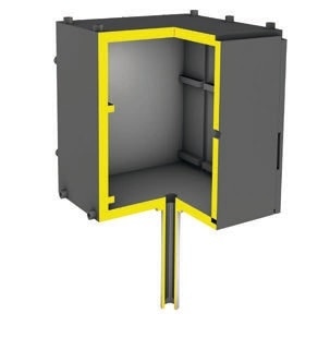
Figure 8. Schematic view into a retort in a HTK furnace with central gas outlet trough the bottom of the retort.
Figure 9. HTK 25 GR/30 furnace up to 3000 °C with debinding equipment.
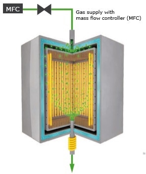
Figure 10. Schematic view into a cold wall chamber furnace HTK equipped with a retort, gas guidance system and heated gas outlet leading to the afterburner.
The volatile organic matter is securely combusted in an active afterburner as seen in Figure 9. Usually, debinding is performed in controlled inert gas atmosphere conditions at temperatures below 800 °C with numerous dwell time steps for debinding various kinds of impurities. After carbonization is completed, the furnace will automatically ramp up to 3000 °C (based on the furnace model) for final graphitization. Figure 12 shows a common debinding process with several dwell times below 800 °C, integrated with a subsequent graphitization step up to 2800 °C with rapid ramping after total debinding.
Advanced Temperature Measurement up to 3000 °C
For graphitization, a precise temperature measurement at both low and high temperatures is essential. But since thermocouples are not able to measure high temperatures and a pyrometer is not able to accurately measure low temperatures, Carbolite offers an optional sliding thermocouple type S which is situated in the hot zone of the furnace to control and monitor the temperature in a range from room temperature up to 1200 °C (blue temperature values in Figure 12).
At 1200 °C, the sliding thermocouple is moving out of the hot zone and the pyrometer (red temperature values as shown in Figure 12) takes over temperature control. Furthermore, a rough calibration and proof of the accuracy of the pyrometer is possible by comparing the temperatures measured by the sliding thermocouple and the pyrometer in the overlapping temperature range between 1000 °C and 1200 °C.
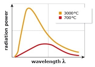
Figure 11. Schematic comparison of the radiation intensities at 700 °C and 3000 °C inside a Carbolite graphite furnace measurable with a pyrometer.
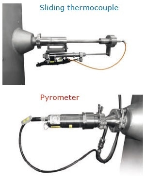
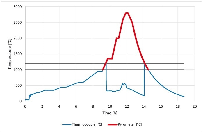
Figure 12. Temperatures measured by a sliding thermocouple (blue) and a pyrometer (red) during a graphitization run up to 2800 °C. Simultaneous temperature measurement between 1000 °C and 1200 °C.
After a short period of dwelling at maximum temperature of 2800 °C, the furnace naturally cools down until the door can be opened at a temperature below 200 °C. A long dwell time at high temperatures above 2800 °C is not required for graphitization, at those temperatures the graphitization process is very fast.
High Quality Heating Elements and Insulation for Superior Temperature Uniformity
For maximum quality in graphitization, all materials in direct contact with the customer’s graphite parts must be as clean as possible. The hot zones of all Carbolite graphite furnaces are built solely of pure graphite materials.
Within the water-cooled stainless steel vessel, all graphite parts are built for maximum mechanical stability. Surrounding the heating elements Carbolite fitted high quality graphite felt insulation for maximum sample temperature consistency (Figure 13 and 17). An optional graphite retort can be specified to guard the heating elements from wear in case of sample outgassing (see above).
For the top loader furnace LHTG (refer Figure 14) a circular mantle heater in an ideally symmetrically meander is fitted. This kind of arrangement is positioned around the sample like a belt, while the upper roof and lower bottom of the usable space is securely sealed with graphite felt insulation.
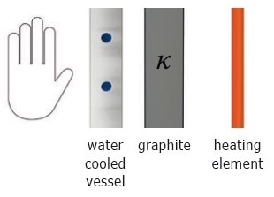
Figure 13. Schematic heating concept of graphite heating elements and graphite felt insulation within the water-cooled furnace vessel.
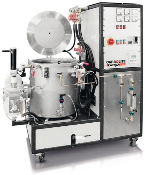
Figure 14. Top loader furnace LHTG up to 3000 °C.
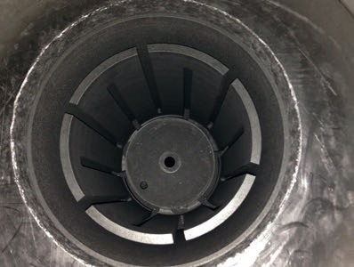
Figure 15. View from above onto the circular heater of the LHTG furnaces, here with central gas outlet in the middle of the bottom.
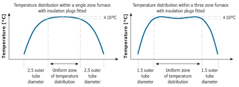
Figure 16. General difference of the uniformity between a single and three zone furnace.
For the front loader HTK, Carbolite offers door and back wall heater in a three zone arrangement as an option to boost the consistency (refer to Figure 18). Each of the extra zones has either a pyrometer or a thermocouple for separate temperature control. Typically, the door and back wall zones are set to marginally higher temperatures during heat treatment to enhance the uniformity even further (refer Figure 16).
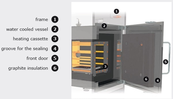
Figure 17. View into a graphite HTK chamber furnace.
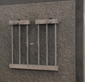
Figure 18. Door heater of an HTK furnace.
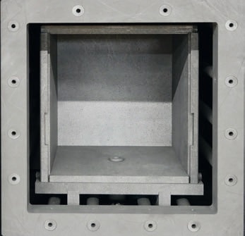
Figure 19. HTK 8 mantle heater with opened retort.
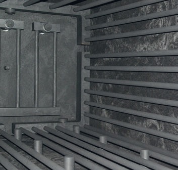
Figure 20. View into HTK 400 mantle heater with back wall heating and several graphite pillars at the bottom supporting the movable retort for convenient loading and unloading of the furnace.
In case of the front loader furnaces of the HTK range, the standard is a mantle heater that applies heat symmetrically from four sides (left, right, above and below. For small volumes, one heating zone enclosing the sample is provided. However, for larger furnaces, multiple heating zones are available as seen in Figure 16.
Controlled Atmosphere, Partial Pressure and Vacuum in Carbolite Furnaces during Heat Treatment
Carbolite offers all types of atmospheres to suit the customer’s requirements during the graphitization process. However, at maximum temperatures above 2200 °C, it is strongly advised to use only Argon at 1 atm. In general, the definition of heat treatment in controlled atmosphere is to retain the purity of the used inert (N2 or Argon) or reactive gas (e.g. H2, CO, CO2 and many others on request) which flows through the furnace, as seen in Figure 21.
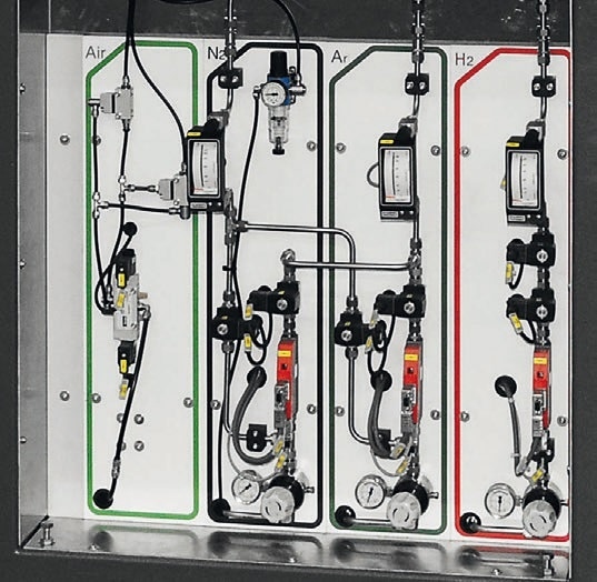
Figure 21. Fully automated multiple gas controls by MFC at a Carbolite graphite chamber furnace, air is only used for pneumatic valves.
The gas is purged within the furnace, producing a gentle overpressure, and is discharged again. Before heat treatment, the furnace is evacuated with a vacuum pump. Subsequently, it is purged with inert gas, hence the gas purity is retained. To exchange the atmosphere, it is also possible to just purge the furnace with inert gas without prior evacuation. This is a practical solution for tube furnaces. However, for a chamber furnace having graphite heating elements and graphite felt insulation, evacuation is the only possible solution. The definition of the partial pressure mode is to have a clear inert gas flow at a fixed lower pressure inside the furnace (refer Figure 22).
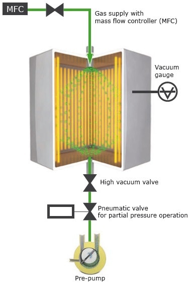
Figure 22. Schematic drawing of the inert gas partial pressure equipment fully automatically controlled by a PLC.
The incoming inert gas flow controlled by a MFC and the pressure may be modified by the user in the program table. A pneumatic valve with valve position indicator in front of the vacuum pump automatically opens and closes precisely to keep the required lower pressure inside the furnace. The pressure can be set between 10 and 1000 mbar (Figure 23). Typically, single or double stage rotary vane pumps are used for limited pressure control of the inert gas.
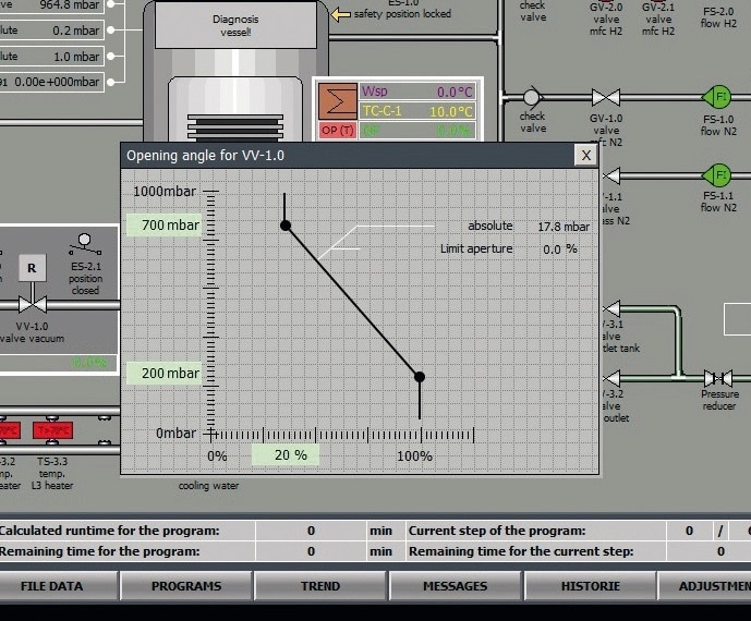
Figure 23. The PLC software adjusts the opening angle of the pneumatic driven ball valve and the MFC so that the desired lower pressure in the furnace is maintained constantly.
The optional vacuum pumps are categorized with a defined end pressure. This is measured in agreement with the PNEUROP standard. Here, the pressure at the pump’s closed flange is measured. Linking the pump to a vacuum recipient like a furnace alters the situation. The working pressure which is accomplished after a specific time depends on a number of factors: The desorption rate of the inner surfaces, leakage rate of the vacuum recipient and possible outgassing from the sample or other devices.
The leakage rate of the recipient is measured and defined by Carbolite. All sealings are prudently selected to offer lowest possible desorption rates. The vacuum devices are cleaned before assembly. Nonetheless, the outgassing from the customer’s sample, the cleanness in the laboratory and the humidity of the ambient air are factors which cannot be controlled.
Carbolite designs the pumping units in such a manner that for clean, cold, dry and empty (ccde) conditions within the furnace, the specified working vacuum is realized in a reasonable time. For ccde conditions, the working vacuum is provided for each pumping unit in the above section. A high vacuum furnace must always be flooded with inert gas. The time the furnace is open and the ambient air affects the interior should be reduced to a minimum.
Conclusion
With all these options available, CARBOLITE is a first-class partner for graphitization solutions up to 3000 °C. The materials used and the smart design of the furnaces in combination with over 30 years of experience in the development of high temperature furnaces make these furnaces the perfect choice for graphitization projects.
See a brief selection of our 3000 °C graphite furnaces in the following table.
| |
HTK 80 GR//30-1G |

LHTG 100-200/30-1G |

LHTG 200-300/30-1G |
| External dimensions |
| H x W x D [mm] |
2500 x 2400 x 2500 |
1800 x 1600 x 1000 |
1800 x 1600 x 1000 |
| Transport weight |
| Complete system [kg] |
4000 |
1000 |
1500 |
| Usable space |
| Volume [l] |
80 |
1.5 |
9.4 |
| H x W x D, usable space without retort [mm] |
400 x 400 x 500 |
– |
– |
| Ø x H, usable space without retort [mm] |
– |
100 x 200 |
200 x 300 |
| H x W x D, usable space with retort [mm] |
380 x 380 x 480 |
– |
– |
| Ø x H, usable space with retort [mm] |
– |
90 x 200 |
180 x 300 |
| Thermal values |
| Tmax, vacuum [°C] |
2200 |
2200 |
2200 |
| Tmax, atmospheric pressure [°C] |
3000 |
3000 |
3000 |
| ΔT, between 500 °C and 2200 °C [K] (according to DIN 17052) |
± 10 |
± 10 |
± 10 |
| Max. heat-up rate [K/min] |
10 |
20 |
20 |
| Cooling time [h] |
8 |
5 |
7 |
| Connecting values |
| Power [kW] |
250 |
40 |
85 |
| Voltage [V] |
400 (3P) |
400 (3P) |
400 (3P) |
| Current [A] |
3 x 362 |
3 x 310 |
3 x 85 |
| Series fuse [A] |
3 x 400 |
3 x 125 |
3 x 100 |
| Vacuum (option) |
| Leakage rate (clean, cold and empty) [mbar l/s] |
< 5 x 10⁻³ |
| Vacuum range depending on the pumping unit |
rough or fine vacuum |
| Cooling water required |
| Flow [l/min] |
200 |
30 |
75 |
| Max. inlet temperature [°C] |
23 |
23 |
23 |
| Gas supply |
| Nitrogen or Argon flow, others on request [l/h] |
200 – 2000 |
50 – 500 |
50 – 500 |
| Controller |
| Manual operation |
Eurotherm with KP 300 panel |
| Automatic operation |
Siemens |

This information has been sourced, reviewed and adapted from materials provided by CARBOLITE.
For more information on this source, please visit CARBOLITE.