During compression, tensile, and flexure tests, varying material properties require the measurement of force as well as deformation (compressive deformation, extension, deflection, strain) for a specimen under load.
A distinction is made between direct and indirect extension measurement.
Indirect Extension Measurement
Indirect extension measurement involves determining specimen extension by measuring the variation in the distance between the testing machine crossheads. Thus, it includes the deformations of all units within the testing machine load frame. It is essential that the sum of these individual deformations is negligible compared to the extension to be measured, suggesting that either it must be below the permissible measurement error, or it can be partially eliminated through a computed correction curve.
It is possible to determine this correction curve for a particular machine configuration and use it to correct the measured extension values, given that the deformation of the test arrangement is adequately reproducible.
Zwick materials testing machines record the change in crosshead travel (and consequently in crosshead speed) using digital crosshead encoders with very high resolution (better than 0.2 μm for all types of machines).
Extension measurement through crosshead travel may be suitable for the following cases:
- Compression tests on specimens with high deformation (for example, from 30 to 50 mm)
- Compression tests where it is possible to compensate for the effects of the test arrangement through a correction curve
- Non-flowing, stable materials
- Strip specimens and parallel clamped specimen grips which ensure defined grip-to-grip separations and the specimen has non-flowing, stable characteristics
- Characteristic values with high strains (strain at break)
Direct Extension Measurement
Direct extension measurement on the specimen removes all undesirable side effects, such as load-cell deformation, load-frame deformation (columns, lead-screws, crossheads), deformation of the specimen grips, and any specimen slippage.
Zwick offers measurement systems for the following:
- Deformation measurement for flexure and compression tests
- Transverse strain measurement (measurement perpendicular to the tensile direction)
- Axial strain measurement (measurement in tensile direction)
Direct extension measurement is always essential if:
- Elastic deformation of machine components should not distort the result
- The result could be distorted by the specimen behavior in the clamping area, specifically with soft materials
- Required by the relevant test standard
- Specimen deformation exterior to the gage length is not to be included
- Self-clamping specimen grips are employed and movement of the jaw inserts is not to be included
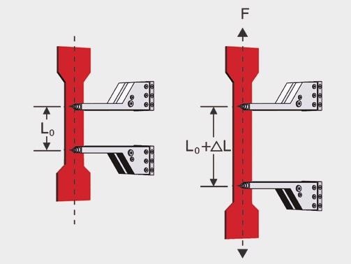
Direct extension measurement
Relevant Material Properties
Extension Measurement
Based on the material properties to be determined, extension measurement during loading up to specimen break can be classified into various ranges:
- Determination of offset yield from the beginning of permanent deformation
- Fine strain measurements in the elastic range and at the start of the permanent deformation range
- Determination of uniform strain and strain at break
Fine Strain Measurement
This is mainly used to determine the technical elastic limit (0.01 % proof strength) and Young’s modulus for metals and Young’s modulus for plastics. The typical strain range to be measured here is in the range of 0.05% to 0.25% (also up to 1% for films/foils).
These material properties necessitate the measurement of very small extensions at proportionately high resolution and extremely small errors. In addition to clip-on and sensor-arm extensometers (multiXtens, makroXtens), laserXtens and videoXtens are ideal according ISO 9513 (see the image below).
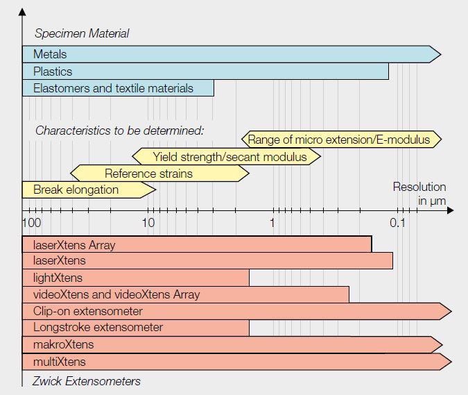
Range of application of Zwick extensometers based on resolution
Determination of Offset Yield (Proof Strength)
When testing plastics or metals, if the transition from the elastic to the plastic range is continuous in the stress-strain diagram, offset yields are determined for characterizing the materials.
Offset yield (see the image above) can be determined by using all sensor-arm extensometers, analog and digital clip-on extensometers, and non-contact measurement systems, for example, videoXtens, laserXtens, and lightXtens.
Uniform Strain and Strain at Break
Uniform strain, which is the non-proportional strain under loading at maximum force, is determined for metals. Direct extension measurement allows continuous testing from the elastic range up to specimen break.
Strain at break is the permanent extension, relating to the initial gage length on the specimen following break. In order to determine strain at break, it is necessary to design an extensometer such that it has a long measurement travel for testing up to specimen break. The most suitable types for this are non-contact measurement systems and sensor-arm extensometers with swiveling knife edges. Clip-on extensometers are suitable only to a limited extent for the determination of strain at break.
Transverse Strain Measurement
Poisson’s Ratio (μ)
A measure of the deformation ratio between axial and transverse strain in a tensile test is referred to as Poisson’s ratio μ. Testing long-fiber reinforced plastics is the preferred use of Poisson’s ratio. Two strain measurement systems with the ability to operate in both axes at the same time are needed to measure Poisson’s ratio.
The solutions offered by Zwick include video-based non-contact transverse strain measurement system (videoXtens transverse strain extensometer) or digital and analog transverse strain extensometers. The transverse strain extensometers are used in combination with a sensor arm extensometer (multiXtens, makroXtens).
Vertical Anisotropy (r-Value)
Vertical anisotropy involves characterization of the cold workability of thin sheet metal in relation to the behavior of the material at the time of deep drawing. The r-value represents the resistance of sheet metal to a decrease in thickness during single-axis tensile loading. Transverse strain should be measured on a dumbbell specimen in order to determine these values.
A combination of a digital or analog transverse strain extensometer with the makroXtens is ideal for this.
The videoXtens transverse strain extensometer, Zwick’s video-based non-contact transverse strain measurement system can be used as an alternative.
The biaxial digital clip-on extensometer is particularly proposed for vertical anisotropy test and is designed for transverse and axial strain measurement.
Selection Criteria
A basic decision to be taken is whether direct extension measurement is needed, or whether it is enough to measure indirect extension via crosshead travel.
It is essential to choose an extensometer with the suitable characteristics in order to use direct measurement. Some of the criteria that determine this selection are given below, based on the material to be tested and the results to be determined.
Initial Gage Length (Le)
Depending on the shape and dimensions of the to-be-tested specimen, a range of initial gage lengths are recommended by test standards. In a majority of the cases, the gage length is comparatively small for higher strain levels and quite large for lower strain levels. In the case of metals testing, the initial gage length is in direct association with the cross-section of the specimen (for proportional specimens).
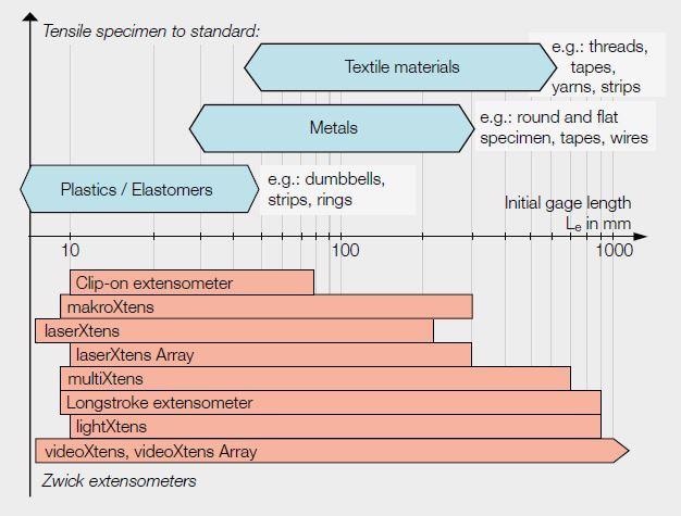
Range of application of Zwick extensometers based on initial gage length
Measurement Travel
It is essential that the extensometer measurement travel is adequate for the to-be-tested specimen. For an unknown specimen strain, it can be estimated for different materials and characteristic values (see the image below).
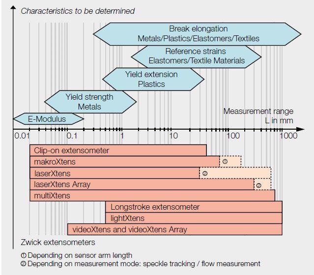
Range of application of Zwick extensometers based on measurement travel
Type of Loading
The type of loading also has an impact on the measurement range. The requirements for cyclic or compression tests and for tensile testing are different, for instance, it is necessary for extensometers employed for cyclic tests to have zero mechanical hysteresis.
Resolution and Accuracy
It is important to observe the resolutions and accuracy levels stipulated in the individual test.
Specimen Break
The extensometer must be protected from high specimen resilience at break and the ensuing high acceleration forces.
Specimens prone to a whiplash effect at break, including straps, ropes, and elastomers, face this risk. Non-contact measurement systems are appropriate for such tests.
Sensor arm extensometers from Zwick come with swiveling knife edges and sensor arms. During the specimen break, they move aside and out of the way to prevent damage to the extensometer.
Notch and Flexure Sensitivity
Furthermore, the notch and flexural sensitivity of the specimen material decides the selection of extensometer. The weight or possible weight compensation has an influence on the design of a clip-on extensometer (specimen loading via torque), which is attached directly to the specimen, whereas the manner in which it is attached influences the test. For instance, the application of optional counter-rollers to specimens with thin cross-sections could result in distortion of the test results.
Drag Forces
It is essential that the drag forces of clip-on and sensor-arm extensometers are as low as possible to avoid any effect on the specimen — guaranteed with Zwick extensometers.
Edge-Fiber Strain
The material and the specimen shape offer signs of the possible existence of differing edge fiber strain, which must be enabled during strain measurement by averaging. For instance, differing edge fiber strains take place as a result of imprecise axial clamping of the specimen or loading specimens with flexural stresses (with single-sided clip-on extensometers with long levers or with only one counter-roller).
Testing in Temperature Chambers
Non-contact extensometers or extensometers with extended sensor arms must be used for deformation measurement in temperature chambers.

This information has been sourced, reviewed and adapted from materials provided byZwickRoell GmbH Co. KG.
For more information on this source, please visit ZwickRoell GmbH Co. KG