Topography becomes more important in quality assurance for manufacturing. This regards the characterization of macro-sized to medium optics and the optimization of a manufacturing process using a coherence scanning interferometer, e.g., the measurement of touch points that directly relate to the polishing process and how to better optimize the manufacturing.
Profiles or simple flatness measurements are not sufficient and areal measurements by line profiler or microscope-based systems are time consuming. Quality assurance in manufacturing is cost sensitive, especially, when a 100% control and optimization is needed. A macro lens optical metrology tool can overcome these disadvantages. We investigated the use of a large area coherence scanning interferometer for manufacturing, including measurements. Depending on the tolerances of parameter and the given cycle-time, solutions are presented on how to provide important measurement feedback to the manufacturing process.
Introduction
Today many work-pieces have to be manufactured with high accuracy and very tight tolerances. In many industries: optics, electronics, semiconductor and mechanical components are finished using a polishing process. This is a straight forward and commonly used finishing process; however, complications occur when you start to work with precious materials and expensive coatings. In order to have a fast response to component preparation for polishing optimisation, metrology feedback is often required. The measurements should be done very often close to the manufacturing line and in some cases, if a 100% control of the parts is needed, near on-line. Note: This is a challenge for the metrology, because additional requirements such as environmental conditions like vibrations, dust, temperature changes are much worse compared to conditions in laboratories. Not only do you need to consider outside influences on the measurement, more importantly the actual measurement instruments window of XYZ operation and functionality should be considered. Traditional methods of measurement within the optics industry would consider a microscope based roughness tester and for flatness a traditional Fizeau interferometer. These technologies may prove fine for singular components but when presented with a cluster of components that are all polished on the same base plate then these commonly used instrument types can out stretch their XYZ performance envelopes. In the following sections investigations of the optimization of a manufacturing process using a macro lens large area Coherence Scanning Interferometer (or White light Interferometer) is described.
What is Optical Polishing?
The aim of advanced optical fabrication is to produce highly accurate optical surfaces. Polishing is a method used to produce high quality surface finishes by removing the rough or damaged layers, improving and smoothening the final surface to that of a high quality finish. Polishing involves the use of free grains, usually suspended in a liquid rather than bonded into a wheel as in grinding. This is a process associated with the generation of nominally ideally smooth surfaces.
High precision optical components are made using many materials from glass through to metals. These components are typically finished with a polishing process in order to meet optical surface finish requirements.
The superior surface finish capability of polishing has allowed this technique to be widely adopted for the manufacture of precision mechanical and optical components.
Surface Inspection, Limitations and Problems
Surfaces will need to be inspected for both smoothness and flatness. The smoothness is typically measured using a microscope base roughness tester and the flatness with a larger aperture Fizeau interferometer. For microscopes to make measurements of larger surfaces some kind of image stitching is always required, when you consider the operational field of view then to stitch large areas will be both time consuming, have question marks over accuracy and limitations on practical data set sizes. For flatness measurements of singular components then these are commonly measured using a Fizeau type interferometer but when presented with a cluster of components that are all polished on the same base plate then this commonly used instrument can out stretch its XYZ performance envelope. Fizeau interferometers use an interference technique to analysis the transmitted wavefront using a phase shifting method. This traditional phase shifting method works well for the measurement of a singular flat smooth surface but cannot be used to measure islands of information, broken, disconnected surfaces or large step heights. Thus, it is very difficult to inter-relate different flat components and to be able to determine their inter height and angular surface relationship with each other.
So problems come in the manufacturing process when it is required to measure, understand, control and improve a manufacturing process where smaller optical components are all clustered together. These will be made simultaneously on a singular mounting block, as is common practice in the optics, electrical or semiconductor manufacturing industries. When finishing multiple surfaces mounted on a singular optical mounting block, problems can arise for how each component is inter-related in terms of height and angles. These small difference can be taken care of with a long enough polishing process but if you have tight tolerances or surfaces with thin coatings consisting of precious materials, expensive coatings, critical large step heights or tight component thicknesses. Then it could prove very time consuming, expensive and failed parts; where expensive coatings are completely polished away or thicknesses prove out of tolerance – giving to failed components.
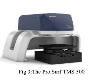
Macro Lens Metrology - Pro.Surf TMS 500
Polytec has long been associated with world-leading metrology for optical components, and now introduces the Pro.Surf TMS 500. The Pro.Surf TMS 500 is the newly developed non-contact Coherence Scanning Interferometer (CSI).
This instrument is of a macro lens optical configuration, meaning it has a large Single field of view, up to 44.9 mm x 33.8 mm. With image stitching, areas of up to 228 mm x 221 mm can be measured. The maximum standoff distance is 83 mm, the step height range is up to 70 mm and the Z resolution is to the nano-meter sensitivity level, making it an interesting measurement tool for precision optical components. It is worth noting that extremely good step height measurement uncertainties on large steps can be achieved, e.g. maximum deviation of 0.07 µm on a 1 mm step measurement is possible but needs to be discuss closely with Polytec.
In Summary, the Pro.Surf TMS 500 has some novel XYZ measurement capabilities. The instrument can generate a 3D representation of a structure by scanning the macro lens CSI fringes through the surface in a ‘Z’ direction. Then processing this information to transform the data into a quantitative 3D image, while still being able to inter-relate surfaces, angles, steps, flatness and parallelisms. The Pro.Surf TMS 500 is specifically designed to measure large steps and flat surfaces to a tight measurement tolerance with stable repeatability.
Case Study: Optical Polishing with Multiple Optics
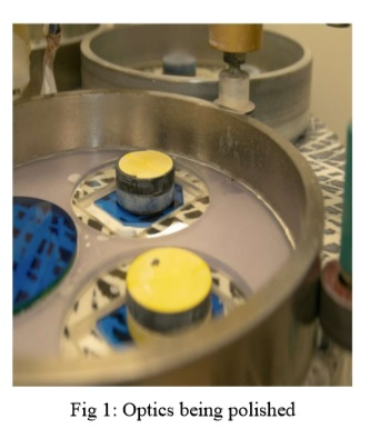
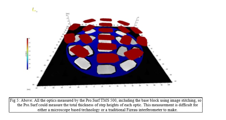
The measurement task was to assess the level of each optic and to use this information to help optimise the manufacturing process. The manufacturer has the problem that the optics are mounted onto a base block ready for polishing and these optics have a 25 µm thick coating of a precious material. Once all the individual optics are mounted, the block with optics is then placed upside down onto the polishing machine. The manufacturer wanted to know the peak contact points that come into contact when placed on to the polishing machine. So the inter-surface height and angle of each component should be assessed. Each individual optic had to be placed within a 25 µm height, flatness and angle tolerance or the polishing process could completely remove some of the coatings leading to component rejects.

For 3-D topography measurements, mostly optical methods are required. With high imaging gathering density in both horizontal X and Y surface directions, large amounts of data can quickly be collected. E.g. using a 2 MB camera within the instrument, 2 million independent data points are simultaneously acquired. By principle, the vertical accuracy of interferometers is independent from the field of view. Therefore, surface form parameters over larger areas can be characterized in a very accurate way. This is in contrast to single wavelengths Fizeau interferometers that can only measure flatness, by using White Light Interferometers both rough and smooth surfaces with steps or discontinuities can be investigated, so these instruments became very useful for research and quality assurance.
White Light Interferometers deliver a fast result and independent of a given camera frame rate large step jumps in the scanning direction accelerates the measurements. Using a medium aperture coherence scanning interferometer (Polytec Pro.Surf TMS 500) with a 44.9 mm x 33.8 mm macro lens field of view large areas are quickly measured. Larger objects can be measured using image stitching.
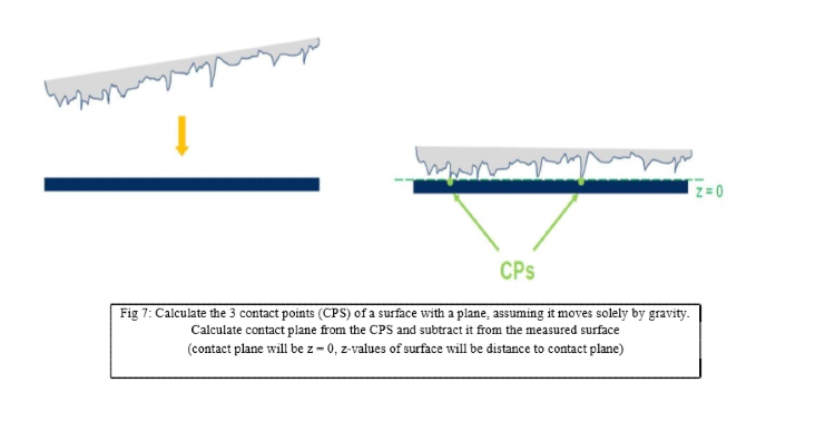
Gravity Mindful Levelling Algorithm
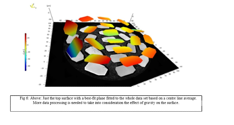
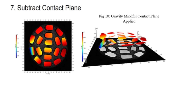
If a simple best-fit plane is simply fitted to the data then this centre-line average is unlikely to reflect the effect that gravity will have on the surface and not communicate very well how the gravitational contact points will relate to the polishing process. In order to meet the requirements of polish control on a 25 µm thick coating a new surface levelling algorithm had to be developed. Its goal is to calculate the three contact points of a surface with a plane, assuming the sample moves solely by gravity.
The Calculation of the Contact Plane
Below are the processing steps:
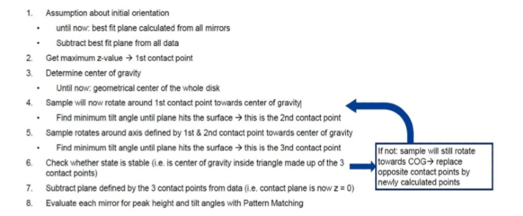
Note: Pattern matching and automation routines can now be applied to any data. Go/No Go data processing is fully possible, including flatness, steps, parallelism, angles and even texture parameters.
Level Testing
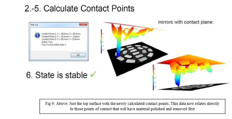
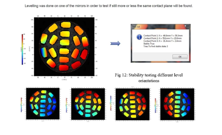
In order to test the stability of the algorithm, different initial orientations of the measured surface have been used as input. It was found, for this sample, that the same contact plane was calculated, no matter the initial orientation (see figures below for examples). For some initial orientations (especially with higher tilt angles) the number of tries to find a stable state increased. However, it was never higher than 15 and thus, the algorithm performed fast under any circumstances
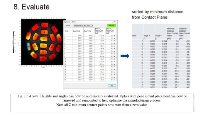
Above: Heights and angles can now be numerically evaluated. Optics with poor mount placement can now be removed and remounted to help optimise the manufacturing process. Note all Z minimum contact points now start from a zero value.
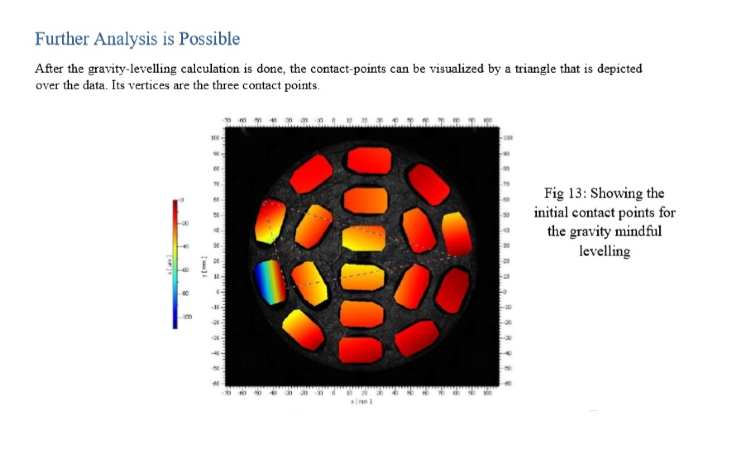
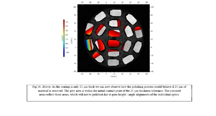
Further analysis is now possible. To investigate which areas of the optics are first removed when polishing a z-distance clipping filter can be used. In the figure below all data within a 25µm distance from the zero contact point has been removed (grey colour). While optics with no more data points are now considered polished, the areas that have colour remain untouched by the polishing tool. Thus, assuming a 25µm valuable coating, this arrangement of optics cannot be polished without removing the coating at some areas and not others leaving to problem of components being rejected.
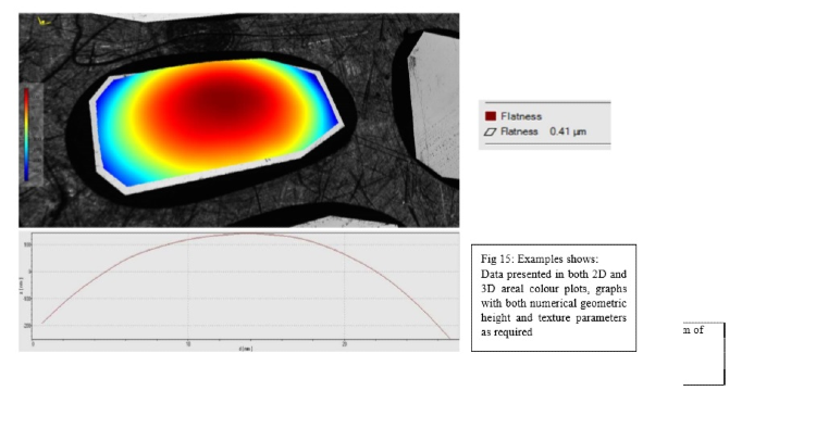
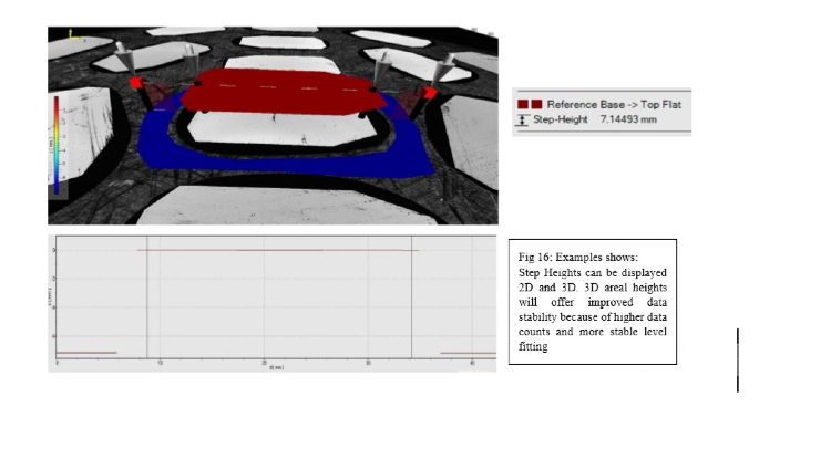
Additional Flatness and Step Height Measurement of Optics
As well as measuring and identification of the level of the inter-surface height relationship of each optic. The flatness and step height of each optical surface can be analysed individually. Both 2D and 3D areal colour plots can be displayed and numerically processed. 3D areal heights will offer improved data stability over 2D plots because of higher data counts and more stable level fitting.
Measurement Considerations
The measurement of these 25 µm thick-coated surfaces are numerically processed to provide a direct insight to the effect of the polishing process. How much material will be removed can be observed through total step height measurement and which optics need to be re-mounted can be numerically identified to help avoid the complete removal of a coating or the part polishing of a coating. Such small height differences can be measured over a scan range of 70mm by the telecentric beam path. The lateral resolution, however, of a telecentric macro lens set-up is larger than that of a microscopic set-up due to the small numerical aperture but in this case, the finer spatial frequency information was not required.
One important influence is external or induced environmental vibrations, which change the distance between the measured surface, the work-piece fixturing and the measuring instrument. As White Light Interferometry is a scanning method, the instrument interprets the relative motion between instrument and sample during the measurement as wavy surface if vibrations are present. These externally generated vibrations can be suppressed by an active vibration control and/or by software algorithms.
Another important issue is the automation, especially, when in-line measurements or “one button” routine measurements are required. Here the measurement and evaluation algorithm should be very stable, settings are defined by an administrator or expert through a recipe based teach and learn software concept. Roughness values maybe influenced by spiking, especially, if they have a similar size as the roughness itself. In addition, very critical for example is single spike, which can lead to a completely wrong result for flatness. Typically these algorithms maybe dependent on the real surfaces and there is no general recipe. With a-prior knowledge not having small and functionality-influencing structures it is sometimes useful not only to remove single spikes but also to apply a longer wavelengths low-pass filter to avoid additional artifacts. With that, e.g., routine measurements are possible and done. In addition, for in-line measurements or measurements close to the production line the influence of the environment have to be taken into account as well.
Conclusion
Medium aperture Coherence Scanning Interferometry is a useful method for both research and industrial quality control, especially in respect to area measurements. Area measurements are needed, because they deliver valuable information within a short measurement time. In certain cases the measurement time can be reduced in order to match cycle times or to increase the number of tested samples. Automatic measurements are possible for in-line and/or sample control close to the production line. However, influences of artifacts and from the environment must be considered. Most importantly, it is critical to consider the XYZ envelop of measurement performance of the metrology tool. Here the Macro lens interferometer scans up to 70 mm in Z range, to a vertical resolution of <1.45 nm and XY area of up to 228 mm x 221 mm in size, critically the coherence scanning macro lens interferometer can process islands of data, flatness and step heights over large areas. As well as the XYZ window of operation, the analysis in relationship to the surface function, its production and creation all have tight tolerances that need to be met. For this test case a 25 µm thick coating needed to be controlled. The special gravity mindful levelling algorithm takes into account how and where material will be removed or not. Finally, other influencers: environmental vibrations, data masking, correct data filtering, automation and robustness testing should all be considered for this particular manufacturing challenge.
References
[1] Dresel T et al. 1992 Applied Optics 31 919.
[2] Malacara D 1992 Twyman-Green Interferometer Optical Shop Testing, Ed. D. Malarca, 2nd Ed. New York : John Wiley & Sons
[3] Bauer, W., 2011 Special Properties of Coherence Scanning Interferometers for large Measurement Volumes, J. Phys.: Conf. Ser. 311 012030
[4] Boedecker, et al. 2011 Calibration of the z-axis for large-scale scanning white light interferometers, J. Phys.: Conf. Ser. 311 01202