Material testing is the part of engineering design, development and research which relies on laboratory testing in order to answer questions. During manufacturing, testing is also needed to ensure a material or product meets a predefined specification.
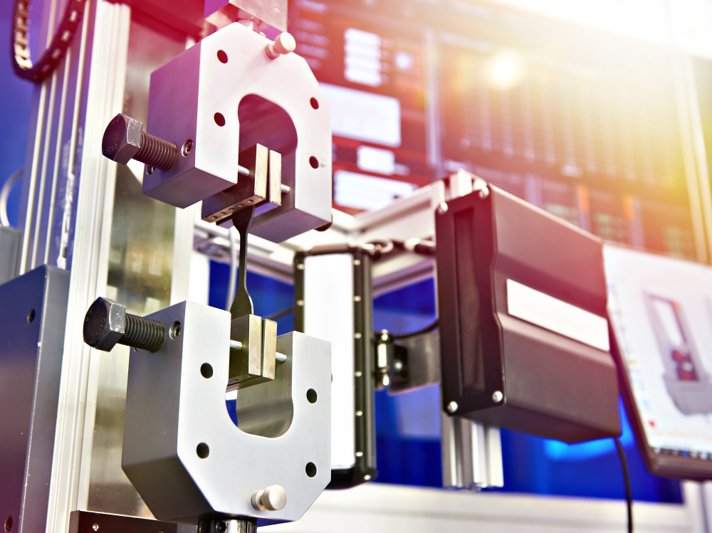
Image Credit: Shutterstock/Sergey Ryzhov
In order to measure the mechanical properties of materials in compression, tension, bending or torsion, a universal testing machine is utilized. This article outlines the two different types (hydraulic and electromechanical) of universal testing machines and why repeatability, accuracy, and resolution are crucial for gathering the correct test results.
Mechanical testing requires some understanding of the planning, execution, and evaluation of experiments, in addition to familiarity with measurement systems. Sometimes a company's test results do not match results from another lab, or the results they are getting are different than historical values even though their manufacturing process had not changed.
There are two classes of testing machines, electromechanical and hydraulic, how the load is applied is the main difference.
Electromechanical Testing Machines
The electromechanical machine uses a variable speed electric motor, gear reduction system and one, two or four screws to move the crosshead up or down. This motion loads the specimen in compression or tension.
By changing the speed of the motor, a variety of crosshead speeds can be achieved. In order to accurately control the speed of the crosshead, a microprocessor based closed-loop servo system can be implemented.
Anatomy of an electromechanical testing machine. Image Credit: Admet, Inc. - Materials Testing Equipment.
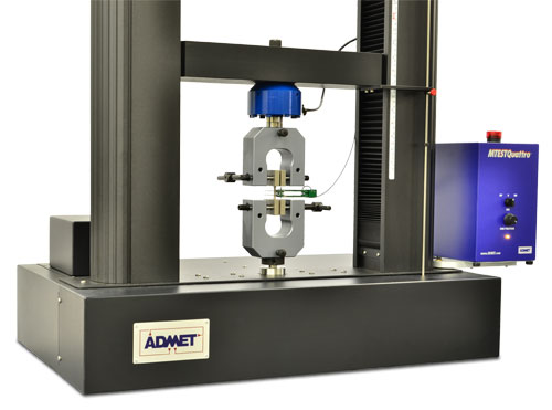
eXpert 2600 Universal Testing Machines
Available in table top or floor standing configurations, eXpert 2600 dual column electromechanical testing systems can go up to 600kN (137,000lbf) force capacity. The servo-control motor enables the user to run tests at very slow net deflection rates.
eXpert 7600 Universal Testing Machines
eXpert 7600 single column electromechanical universal testing machines come in force capacities up to 5 kN (1,125 lbf). These units feature the industry’s largest vertical test space, and fit within a 431x520 mm space, making them perfect for testing high elongation materials like rubber.
eXpert 5000 Universal Testing Machines
eXpert 5000 series electromechanical testing machines feature modular single and dual column frame components, base plates and detachable actuators. This setup provides the ability to configure a system in a number of horizontal or vertical orientations for a large scope of applications.
The ASTM D3574 foam testing configuration for static and dynamic testing in tension and compression directions is a common configuration with the eXpert 5000 systems.
eXpert 4000 MicroTester
eXpert 4000 electromechanical micro testing systems are ideal for testing small-sized samples of tissue, biomaterials, bone, thin films, fibers, threads, metals, gels and wire, to name a few.
The eXpert 4000 MicroTest systems are adaptable to a variety of high magnification imaging systems, with force capacities up to 5 kN and a large range of fixtures, grips, heating and cooling chambers and fluid baths.
Hydraulic Testing Machines
A hydraulic testing machine uses either a dual or single acting piston in order to move the crosshead up or down. Most static hydraulic testing machines utilize a single acting piston or ram.
In a closed loop hydraulic servo system, the needle valve is replaced by an electrically operated servovalve for precise control. In a manually operated machine, the operator adjusts the orifice of a pressure compensated needle valve in order to control the rate of loading.
All ADMET testing machines use a closed loop system which transfers information from the closed-loop controller to the motor and also from the motor to the closed-loop controller continuously.
This constant feedback enables certain variables like the stress rate and the load rate to remain as specified throughout the tests. Due to their ability to react immediately to possible changes, closed-loop systems supply higher accuracy.
Anatomy of a hydraulic testing machine. Image Credit: Admet, Inc. - Materials Testing Equipment.
eXpert 1000 Universal Testing Machines
eXpert 1000 servo-hydraulic testing systems are perfect for testing composites, metals, medical devices and implants, webbing, concrete, and other materials at extremely high load capacities.
For direct measurement of force, each frame uses strain gauge load cells. These frames provide exceptional precision and accuracy while reducing long-term calibration and service costs, there is no need to compensate for piston friction and other non-linearities.
The eXpert 1900 series is configured to meet the force-stroke-frequency requirements of fatigue testing applications, whereas the eXpert 1600 series is designed for static testing.
Quick Tip
Typically the electromechanical machine is capable of a bigger range of test speeds and longer crosshead displacements, yet the hydraulic machine is a more cost effective solution for producing higher forces.
Accuracy, Repeatability and Resolution
These are the three basic definitions to remember with respect to how well a testing machine can measure stress and strain.
- Accuracy is the ability to tell the true position of the crosshead, it is the maximum error between any two crosshead positions.
- Repeatability is the error between a number of successive attempts to move the crosshead to the same position. Repeatability (precision) is the ability of the crosshead to return to the same position over and over again.
- Resolution is the bigger of the smallest programmable steps in crosshead position or the smallest mechanical step the crosshead can make.
Factors that Affect Accuracy, Repeatability and Resolution
A good test engineer must possess an excellent understanding of the sources of errors that could be introduced during a test. Before testing begins, the test engineer should consider the choice of sensors and measurement instruments keeping in mind the accuracy and suitability of each.
To acquire accurate measurements, the user should know how to measure the errors in order to keep them from creeping into the results. Sensors are key to all mechanical testing measurements.
The power transmission, test frame, grips and fixtures also influence the repeatability and accuracy of its sensors. Sensors that are heated up, are mounted in the wrong position, or are deformed by mounting bolts all cause measurement errors.
eXpert 2600 with manual vise grips and an axial extensometer. Image Credit: Admet, Inc. - Materials Testing Equipment.
The most crucial consideration in mounting a sensor is where to mount it in order to ensure that the desired quantity is measured accurately. One thing to consider is whether the sensor should be mounted on the input or output ends of a transmission.
The resolution of the system will be enhanced by a factor equal to the transmission ratio if the sensor is mounted on the input end of a transmission along with a motor. Yet, backlash and compliance in the transmission, test frame, ballscrews, belts, grips and fixtures will also influence the output of the sensor.
If the sensor is mounted on the output end of the transmission on the other hand, it will measure the process more accurately but the resolution will be reduced.
Sensor Location in ASTM D790 Plastics Bend Testing
ASTM D790 governs the determination of the flexural modulus of unreinforced and reinforced plastics. The test setup requires a three point bend fixture with the loading nose midway between the supports.
The loading nose contacts the rectangular specimen at point 4 and is directly connected to the load cell. The test procedure consists of deflecting the specimen until a maximum strain is reached or until rupture happens in the outer surface of the test specimen.
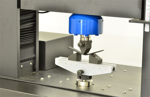
3-Point Bend Test Setup on a Dual Column eXpert 2600. Image Credit: Admet, Inc. - Materials Testing Equipment.
Secant modulus, tangent modulus, and chord modulus are three properties of interest. All three require accurate force and flexural strain measurements in order to acquire proper modulus readings.
All force measurements should accurately represent the applied force if the load cell has been verified to meet ASTM E4 accuracy requirements. Flexural strain is directly related to the deflection of the specimen at the point midway between the supports.
Example 1 – Using the Rotary Encoder Mounted on the Motor to Measure Flexural Strain
Most modern day electromechanical testing machines measure linear crosshead position using a rotary encoder mounted to the motor.
The right angle transmission, moving crosshead, tapered roller bearings, motor shaft, synchronous belt, ballnut, ballscrew, load cell and loading nose are between the rotary encoder and the test specimen. When a force is applied to the specimen, strain measurement errors are presented by the following:
- Stretch in the synchronous drive belt – Torsional compliance and mechanical backlash between mating gears in the right angle transmission.
- Backlash in the ballnuts. When in the unloaded condition, gravity will cause the ball bearings in the ballnuts to be in contact with the upper bearing race. When the applied compressive load surpasses the weight of the moving crosshead, loading nose and load cell, the ball bearings will switch to contacting the lower bearing race.
- Compliance in the moving crosshead, loading nose, load cell, specimen supports and machine base. No machine component is truly rigid, each component can be thought of as a spring.
- Torsional compliance in the motor shaft due to the applied torque. One can think of the motor shaft as a torsion spring with a certain amount of torsional stiffness, as no machine component is truly rigid.
- Compliance and lead error in the ballscrews. A compressive load applied to the specimen will create a tensile load in the ballscrews which will cause them to stretch.
- Compliance in the tapered roller bearings. Tapered roller bearings deform non-linearily, particularly at loads which are a fraction of their rating. Preloading the bearings cause a proportionately smaller amount of deflection but may decrease the effective repeatability and resolution of the moving crosshead.
With these points in mind, the key question is: “How big is the total error compared to the strain I am trying to measure?” There is no clear cut answer but this technique for measuring flexural strain could be used if the overall stiffness of the machine is much greater than the stiffness of the specimen.
Before measuring the flexural strain with the motor encoder a careful analysis of the test setup would be in order.
Note: If one could replace the test specimen with a specimen that was infinitely rigid, the load vs. strain curve as measured by the rotary encoder would be non-linear. The non-linearities make it very difficult to map out the machine errors in software.
Example 2 – Using a Linear Displacement Transducer between the Moving Crosshead and Top Bracket to Measure Flexural Strain
A second method for measuring flexural strain could be to install a linear displacement transducer between the moving crosshead and the top bracket. It is shown as Displacement B in the figure above. For this arrangement, when a force is applied to the specimen, strain measurement errors are introduced by the following:
- Compliance in the load cell, loading nose, moving crosshead, specimen supports and machine base
- Compliance in the ballscrews
- Compliance in the tapered roller bearings
- Backlash in the ballnuts
As the Displacement B Transducer is closer than the rotary encoder to the specimen, there are fewer sources of error. However, like example 1, there is no clear cut answer as to whether the errors introduced by measuring the relative movement between the moving crosshead and top bracket are small enough to be inconsequential. A careful analysis of the test setup and results are in order.
Suggested Techniques for Measuring Flexural Strain
When the techniques utilized to measure flexural strain as outlined in example 1 and 2 are not enough, a device which measures the relative displacement between the underside of the specimen midway between the supports and the machine base is commonly employed. A deflectometer is one such device.
Errors that are introduced by compliance in the supports and machine base are generally a lot smaller than the flexural strain in the specimen. The technique with the smallest measurement error involves attaching two bars on opposite sides of the specimen at points 1 and 2, on the figure above.
Points 1 and 2 are directly above the supports and reside on the neutral axis of the specimen. The bars only contact the specimen at points 1 and 2 and remain straight and unstressed when a load is applied to the specimen. A linear transducer is then affixed to the bar midway between the supports and calculates the deflection of the specimen at point 4.
Conclusion
All experimental measurements include errors. Prior to starting testing, a good test engineer will always ask the question: “Are my measurement errors small enough to not matter?” A good understanding of the sources and magnitudes of the errors is key to making accurate measurements.

This information has been sourced, reviewed and adapted from materials provided by Admet, Inc. - Materials Testing Equipment.
For more information on this source, please visit Admet, Inc. - Materials Testing Equipment.