The 4D InSpec is a handheld surface gauge produced to measure fine-scale surface features and defects in three dimensions on elements made of ceramic, metal, plastic, rubber, composite, and additional materials.

Image Credit: Shutterstock/Kuttelvaserova Stuchelova
Two questions asked in this paper were: is the measurement by 4D InSpec equivalent on the original surface in respect to a replica, that is, how similar are the results? And: under what circumstances should one use a replica instead of measuring directly with 4D InSpec?
Even with 4D InSpec's ability to use fold mirrors to access tight spaces and its small size, some locations are still inaccessible for analysis, for example deep into a range of recesses or in narrow holes. In these situations, replication is required.
The surface feature is coated with a rubber-like paste which is allowed to solidify. It is then taken off and a negative of the feature is replicated for assessment. The method is essentially the same as the one used by dentists to produce a dental mold.
The replicate is commonly analyzed employing a 2D stylus trace. Alternatively, a replica can be cross-sectioned with a razor, and this cross-section is observed on an optical comparator or shadowgraph to predict the depth or height of the feature.
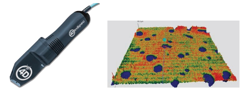
Figure 1: 4D InSpec surface gage (left) and a false-color 3D measurement (right) of pitting on a surface, as taken with the 4D InSpec. Image Credit: 4D Technology
Any production-qualified measurement tool should measure the replicated feature with the same accuracy as it would analyze the surface feature directly. This article will:
- Verify that the total data from direct 3D surface quantification is equivalent to measurements of the replicated features, inside the noise floor of the 4D InSpec gauge, or to approximately 0.0001” (2.5 µm)
- Contrast 3D measurements of a range of surface defects and their replicas and outline the drawbacks of the replication technique.
- Demonstrate how the use of 2D-trace measurement methods (compared to complete 3D analysis of the surface) can result in measurement inaccuracies.
It is well-known that there are costs and limitations involved with replication techniques. A main limitation is when voids are created which cover the deepest parts of the feature when the replication material does not reach all the way to the bottom of deep or steep features.
The process of replication takes an extensive amount of time compared to an optical measurement by 4D InSpec of several seconds for acquisition and an automated pass/fail analysis. Curing usually takes 10 minutes or longer to complete, which is followed by a detailed measurement process using a shadowgraph or optical profilometer that can last up to an hour until results are established.
The costs of replication materials quickly add up as it is a consumable item. Larger manufacturing companies describe spending hundreds of thousands of dollars each year by ordering replication material.
Matching Direct Measurements to Replica Casts
For this report, a range of scratches and pits were replicated. The 4D InSpec was then employed to analyze both the feature directly and its replica. The height of each feature varied from 0.001” (25 µm) deep to 0.007” (178 µm) deep to include various heights as a means to assess the system.
There is a very close correlation between the depth measurements. The slope has an offset of less than 8 micro-inches (0.2 µm) and is 0.998 with an R2 value of 0.9989.
The maximum deviation of any of the replicated measurements compared to the direct measurement was .0001” (2.5µm). This is in the range of the noise floor of the 4D InSpec. Figure 2 outlines the results.
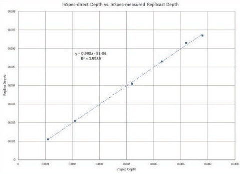
Figure 2: Depth of directly measured features versus replicated surface features using the 3D InSpec analyses. Image Credit: 4D Technology
Example 1: Measurement of a 0.001” Scratch
A scratch with a depth of approximately 0.001” (25 µm) on a visual reference standard (Figure 3), employed for the evaluation of defects, was replicated.
The 4D InSpec was utilized to directly measure the scratch itself, and the cast impression of the replica was also measured. The results of the measurement of the replication and the actual surface measurement are presented in Figures 4 and 5. Of course, where the measurement of the scratch shows a height drop (a negative number), the cast replica represents the scratch as a protruding line, and measurement produces a positive number.
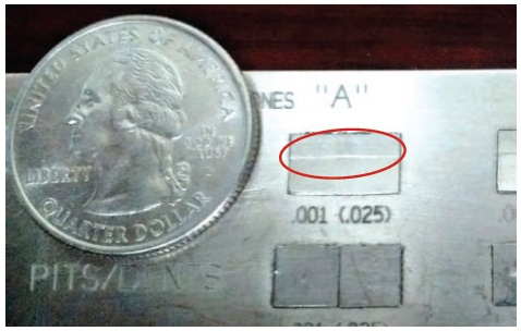
Figure 3: 0.001” scratch on visual comparison standard. Image Credit: 4D Technology
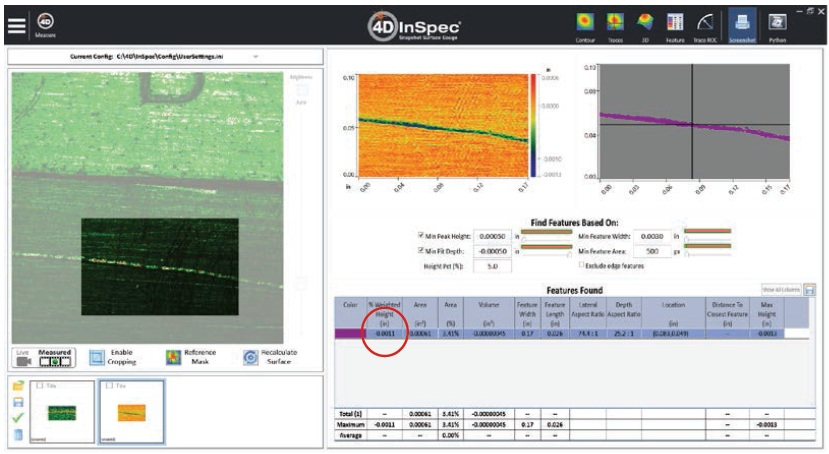
Figure 4: Direct measurement showing bright-field image of scratch (left picture), false-color height map from measurement (center picture) and automatic defect finding and analysis (upper right picture and table below). Image Credit: 4D Technology
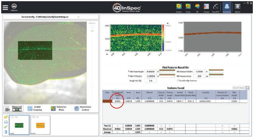
Figure 5: Replicated measurement showing bright-field image of scratch (left picture), false-color height map from measurement (center picture) and automatic defect finding and analysis (upper right picture and table below). Image Credit: 4D Technology
The automatic analysis of the replicated scratch depth and actual scratch depth match exactly in this example. In this case, the errors related to the various materials (and the construction of the replica) are lower than the accuracy of the gauge and are insignificant.
Example 2: Pit Depth Measurements
Four distinct pits and their replicas (Figure 6) were analyzed with the 4D InSpec. The pits were near enough in proximity to fit inside a single field of view of the instrument, which is 0.3” x 0.3” (8 mm x 8 mm). All four pit depths could be analyzed at the same time for this reason.
Inconsistencies between the results from analyzing the initial aluminum surface and the replica are inside the noise floor of the instrument (0.0001”, 2.5 µm). Figures 7 and 8 present the information utilizing the 4D InSpec Feature Analysis tool.
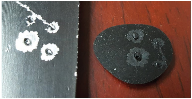
Figure 6: Pitted aluminum sample (left) and its replica (right). Image Credit: 4D Technology
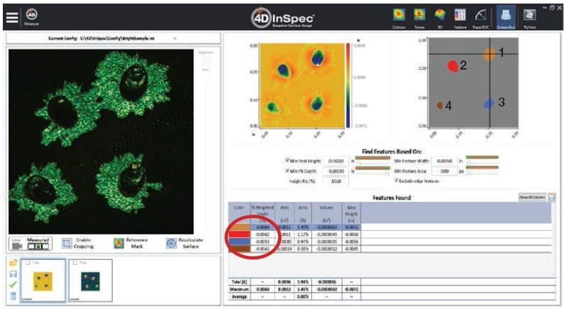
Figure 7: Direct measurement showing bright-field image of pits (left picture), false-color height map from measurement (center picture) and automatic defect finding and analysis (upper right picture and table below). Image Credit: 4D Technology
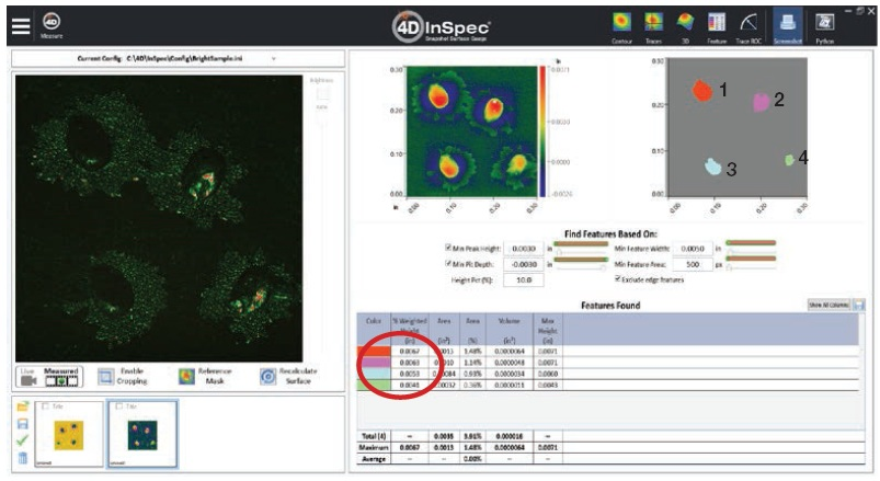
Figure 8: Replica measurement showing bright-field image of pits (left picture), false-color height map from measurement (center picture) and automatic defect finding and analysis (upper right picture and table below). Image Credit: 4D Technology
Limitations of the Replication Method and 2D Analysis of Defects
Voids
A main limitation when replicating defects is that the replica material does not always reach to the lowest region of scratches and pits. This is mainly caused as a result of the material being too viscous, which means it does not travel to the bottom of the feature.
Due to this, a number of organizations that use replication have different formulations with various viscosities in order to select the optimal one for a wide range of defects and parts. Keeping many materials in inventory can be expensive and can also lead to differences in results if the correct material is not utilized.
A further source of an inaccurate replica is that air bubbles may become trapped beneath the material which stops it from moving all the way to the bottom. This can arise regardless of the material viscosity because it is highly reliant on the surface features of the material with the defect.
Figure 9 provides an example of an incorrect replica. A pit with a comparatively flat bottom, ~0.026” (66 µm) deep was directly quantified and a replica was constructed. Figure 10 provides the direct quantification of the pit and Figure 11 presents the replica measurement.
In the top of the replicated surface, there was a depression where the material did not sink all the way to the bottom of the pit. Any calculations of pit depth using this replica would be incorrect.
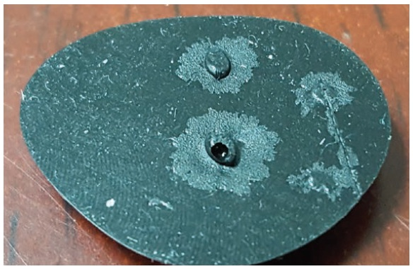
Figure 9: .0026” (66µm) pit in aluminum surface. Image Credit: 4D Technology
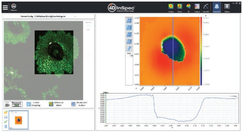
Figure 10: Direct measurement of the pit with 2D cross-section showing a flat bottom. Image Credit: 4D Technology
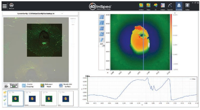
Figure 11: Measurement of the replica with 2D cross-section. The depression in the replica is from the replication material not penetrating all the way down the defect. Image Credit: 4D Technology
Multiple methods were used to confirm that the void was a replicate error as opposed to a feature. Firstly, the 4D InSpec was used to analyze the pit before and after the replica was constructed, and did not observe a feature related to the void. The data is reliable as the feature was easily accessed by the 4D InSpec.
Secondly, visual observation did not find any elevated region in the bottom of the pit that could explain the shape of the replica. Thirdly, a sharp point was moved through the pit and no elevated feature was detected.
Due to the inaccurate replication of the surface, a number of the replicas employed to create the correlation graph had to be remade, indicating that this was not a rare event.
As the process of replication is rather time intensive — taking around 10 minutes to apply and cure the material, having to repeat the construction of replicas can be expensive regarding the turnaround time. This excludes the time taken for the inspector to notice something was inaccurate, and to remake the replica in the first place.
2D vs. 3D Results
2D tools are usually not appropriate for the correct quantification of the depth or height of a feature. Different results will be acquired according to the particular cross-section evaluated, and the location of the selected reference point from which the inspector calculates the height. This is briefly presented in Figure 12.
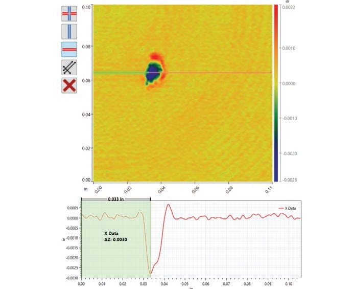
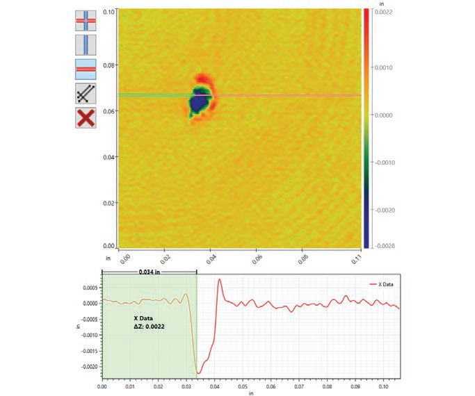
Figure 12: Pit depth measured using 2D cross sections. By slightly offsetting two traces, one gets results that differ by nearly 0.001” (25 µm): the upper result is 0.003” (76 µm) and the lower 0.002” (52 µm). Image Credit: 4D Technology
These variations are even more significant on long features like scratches. It is almost impossible to visually evaluate the deepest area of a scratch and cross-sectioning frequently produces results that are highly variable.
As performed with the 4D InSpec, an analysis of the whole scratch guarantees that the inspector will gather a precise reading of the maximum depth because the complete surface is taken into account.
Conclusions
Replication is sometimes required when analyzing inaccessible areas, even to a handheld tool like the 4D InSpec. The 4D InSpec is equally precise when measuring correctly replicated features as it is with direct measurements.
The process of replication itself is time intensive, in contrast with analysis using a handheld instrument. Replication can result in analysis errors if the replica does not fully reflect the defect to be calculated.
When replication is utilized, analysis should always be performed through the evaluation of the complete 3D defect result instead of utilizing cross-sectioning techniques. Errors in cross-sectioning can emerge as a result of where the 2D cross-section is placed.
Acknowledgments
Produced from materials originally authored by Jared Wheeler from 4D Technology.

This information has been sourced, reviewed and adapted from materials provided by 4D Technology.
For more information on this source, please visit 4D Technology.