Sponsored by InterpowerReviewed by Ify IsiborApr 15 2026
The accurate calculation of cord length and its associated voltage drop are essential to the application of an electrical design.
Background
Using longer cord lengths in an electrical design can introduce challenges significant enough to create potential safety risks. When cable lengths reach 50 feet or more, voltage drop becomes a concern. This occurs due to the resistance of the copper conductors (measured per foot) which can lead to heat buildup over the length of the cable.
Voltage drives electrons through a cable much like water flows through a hose, with both the cable and the hose introducing resistance. In a cable, factors such as conductor size and insulation contribute to this resistance, influencing how easily current can flow.
In alternating current (AC) systems, impedance is a two-component quantity consisting of resistance and reactance. Reactance arises from the electric field generated by changing current. As a result, the applied voltage must be more than the amount of resistance.
When cord lengths exceed 50 feet, heat buildup resulting from voltage drop can become significant enough to damage insulation, potentially leading to melting and, in severe cases, electrical fire. UL testing has confirmed this risk, which is why current ratings are derated for cords of 50 feet or longer.
For example, if voltage drop calculations indicate a value exceeding the 5 % limit specified by NEC Rule 210.19, as well as corresponding CSA requirements, further precautions are necessary.
UL 817 mandates derating of cord sets at lengths beyond 50 feet and again at 100 feet to help mitigate overheating risks. It is also advisable to review the requirements of safety agencies in any countries where longer cords will be used or exported.
Exceeding recommended cord lengths without proper consideration can introduce safety hazards, including increased fire risk and potential equipment damage, while also placing users at risk.
Dan Ford, Technical Support Specialist at Interpower, explains, “The loss of power to equipment reduces the voltage and overall power available to the equipment. If too much voltage is lost, the equipment may not function correctly or may not work at all. For some equipment, such as devices that employ compressors, large motors, or pumps, even a small loss of voltage may cause a problem.”
Interpower’s Policy in Calculating Voltage Drop
The policy at Interpower is to measure voltage drop for assemblies of requested long cord and to notify the customer of any potential issues if the voltage drop could exceed 5 %.
“In those cases,” Ford mentions, “we will let the customer know our findings which are calculated at a full-rated load and ask for details regarding their application’s voltage and current usage. We will then recalculate. If there is still an issue, we can assist the customer in trying to decrease the voltage drop by suggesting alternate, larger cable sizes where possible.”
Increasing cable size or decreasing length are the only two options for decreasing voltage drop. In cases where the voltage drop is too severe – in excess of 8 % – Interpower reserves the right to refuse manufacture of such items due to safety concerns.
Dan Ford, Technical Support Specialist at Interpower
Voltage drop can cause lights to flicker or appliances to overheat, as the load must work harder with reduced voltage. As a general guideline, voltage drop should not exceed 5 %. This can be managed by selecting the appropriate wire size and exercising care when using extension cords and similar components.
Excessive heat buildup in wires or cables can also damage insulation, further increasing the risk of failure.
“The type of damage can range from a degradation (breakdown) of the insulation material to a softening of the material, which could result in tearing if the cable or wire is bent or moved,” Ford said, “or outright melting of the insulation and exposure of the conductor wire beneath. Regardless, this reduces the life of the wire or cable and can lead to other safety issues. Excessive heat build-up can also degrade the conductor material and result in an increase in resistance, which compounds the issue, causing more voltage drop and more heat.”
The material and size of the wire are also critical factors. Copper, for example, is a better conductor than aluminum, resulting in lower voltage drop for the same length and wire size. Higher voltage allows more electrons to flow through the conductor, improving overall efficiency.
Wire size also plays a key role: larger-diameter wires experience less voltage drop than smaller wires of the same length. In the American Wire Gauge (AWG) system, every 6-gauge increase corresponds to a doubling of the wire diameter, while every 3-gauge increase doubles the cross-sectional area.
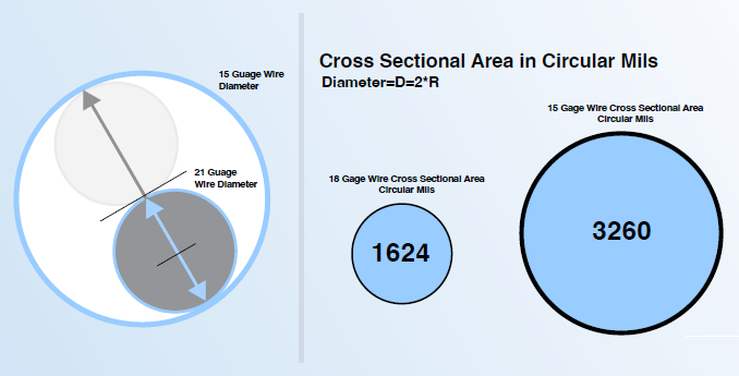
Image Credit: Interpower
The Use of Manual Calculation or The Voltage Drop Calculator
To manually calculate voltage drop, the expected direct current (DC) resistance must first be obtained either from the applicable standard or by measuring the resistance across the cable length.
Standards typically provide this data in ohms per kilometer (Ω/km) or sometimes in ohms per 1000 feet (Ω/1000 ft), so values may need to be converted to ohms per foot (Ω/ft) for practical use.
For North American cable types, Tables 5 and 6 in UL 62 are commonly used to determine resistance values. For international cable types, such as H05VV-F, IEC 60228 Table 1 provides the relevant data.
While these values may not yield exact voltage drop calculations, they are sufficiently accurate to identify potential issues and guide design decisions.
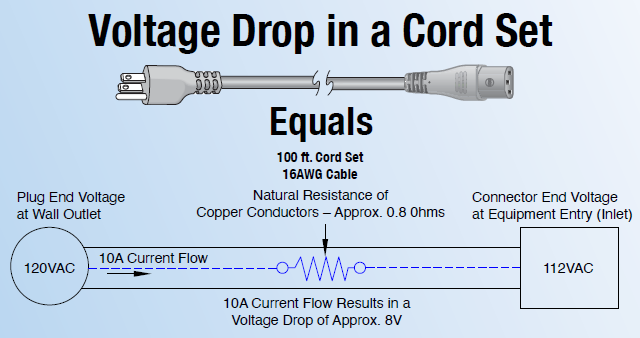
Image Credit: Interpower
Once the resistance in ohms per foot (Ω/ft) for a given cable size is known, it should be multiplied by the total length of the assembly in feet to determine the overall resistance.
The next step is to apply Ohm’s Law: multiply the total resistance by the steady-state current to calculate the voltage drop. If the current is expected to fluctuate during operation, the highest anticipated value should be used.
This calculated voltage drop can then be compared with the mains voltage to determine the remaining voltage available to the load, as well as the overall percentage loss.
Ohms Law: V = IR
V = Voltage
I = Current
R = Resistance

This information has been sourced, reviewed and adapted from materials provided by Interpower.
For more information on this source, please visit Interpower.