The UC Enuity ultramicrotome from Leica Microsystems is well-suited for preparing ultrathin sections of polymer samples under both cryogenic and ambient conditions.
This article presents a series of high-resolution two- and three-dimensional TEM images, highlighting the instrument’s essential contribution to reliable and precise sample preparation in polymer structural analysis.
Background
Polymers underpin a wide range of modern scientific and industrial applications, playing critical roles in packaging, textiles, biomedical devices, advanced electronics, and many more applications.
Their versatility stems from the wide range of morphologies and molecular architectures that polymers can adopt, which in turn define their thermal, mechanical, and functional properties.
The lamellar organization is a key structural feature, particularly in semicrystalline polymers, where it plays a central role in determining performance characteristics such as flexibility, strength, and barrier properties.
It is essential to investigate the internal structure of these materials at the nanoscale to fully understand and optimize them. Transmission electron microscopy (TEM) is highly suited to this purpose, offering the resolution required to visualize fine lamellar arrangements that are typically inaccessible via other techniques.
The preparation of polymer samples for TEM analysis presents distinct challenges, however, due to polymers’ soft, typically heterogeneous nature.
Ultramicrotomy, particularly when performed under cryogenic conditions, can facilitate the production of ultrathin sections able to preserve the material’s native morphology.
Results
Polymer Sample Preparation
Preparing polymers for ultramicrotomy initially begins with the division of the polymers into two classes: rigid and soft.
Rigid materials can often be sectioned directly using an ultramicrotome, typically with a diamond knife. For softer materials, the most critical parameter is the glass transition temperature (Tg), which marks the point at which a polymer transitions from a hard, glassy state to a soft, rubbery one.
In the context of ultramicrotomy, Tg is key to determining the optimal sectioning conditions – specifically, whether sectioning can be performed at room temperature or requires cryogenic conditions. Performing sectioning below the Tg helps reduce deformation and compression, resulting in higher-quality ultrathin sections.
Many other factors impact the sectioning process, including material processing, the presence of blends or composites, and the incorporation of inclusions, nanoparticles, plasticizers, and other additives.
Furthermore, polymers may be stained, typically with osmium tetroxide and/or ruthenium tetroxide, which can alter their brittleness and, in turn, affect their behavior during sectioning.
Sectioning Under Room Temperature or Cryo Conditions
Typical polymer types that can be sectioned at room temperature include polycarbonates, polymethyl methacrylates, stained polypropylene, stained high-density polyethylene, epoxies, nylons, and rigid polyurethanes.
In contrast, materials commonly sectioned under cryogenic conditions include unstained polypropylene, unstained polyethylenes, rubbers, nylons, PVC, flexible polyurethanes, latexes, and unstained ABS.
In this study, poly(styrene)-b-poly(methyl methacrylate) was selected for room-temperature sectioning, while poly(styrene)-b-poly(isoprene) was prepared under cryogenic conditions. The aim was to demonstrate the sectioning quality of the UC Enuity by visualizing the lamellar structure of both polymers using TEM.
Room Temperature Sectioning of Poly(styrene)-b-poly(methyl methacrylate)
The sectioning of poly(styrene)-b-poly(methyl methacrylate) was possible without cryo conditions due to the material’s hardness.
A small amount of the sample was synthesized and embedded in a UV-curable resin to improve its handling. The resin adheres the sample to the sample holder within approximately 10 seconds when exposed to UV light.
The polymer was sectioned at a thickness of 60 nm (Figure 1).
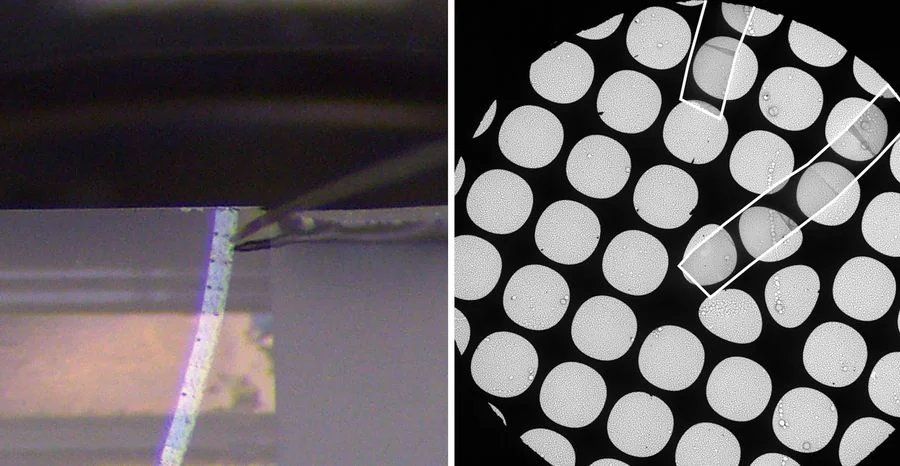
Figure 1. Ribbon of sections of poly(styrene)-b-poly(methyl methacrylate). Left: Sections on water in the knife boat during cutting guided by an eyelash. Right: Sections (white outlines) collected on grids with microgrid support. Image Credit: Akemi Kumagai - Institute of Multidisciplinary Research for Advanced Materials, Tohoku, Japan
The contrast was observed to be relatively weak because the polymer was unstained, but the arrangement of polymer fibers was already visible without phase contrast (Figure 2, left).
The application of phase contrast significantly improved contrast, enhancing the visibility of the regular polymer structure ahead of further analysis (Figure 2, right).
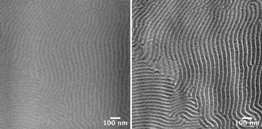
Figure 2. TEM micrographs of poly(styrene)-b-poly(methyl methacrylate). Left: Standard TEM micrograph without phase contrast. Right: Same image position with phase contrast. Image Credit: Akemi Kumagai - Institute of Multidisciplinary Research for Advanced Materials, Tohoku, Japan
Cryosectioning of Poly(styrene)-b-poly(isoprene)
In general, frozen or vitrified samples can be sectioned without resin embedding. However, because the material was synthesized at the laboratory scale, the available sample volume was insufficient for secure handling with standard sample holders.
To address this, the sample was embedded in resin to increase its volume and enable stable fixation onto the sample holder.
A UV-curable resin was used, which hardens within seconds upon UV exposure, and the sample was subsequently mounted onto a cryo sample pin (Figure 3).
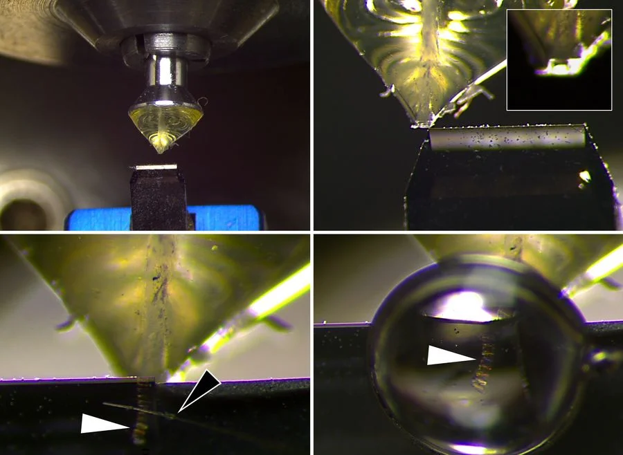
Figure 3. Trimming and sectioning of poly(styrene)-b-poly(isoprene) under cryo conditions. Upper left: Overview of the sample mounted onto a pin and a trimming knife. Upper right: Trimming of the sample towards a block face (insert). Lower left: Ribbon of sections (white arrow) guided by a micrometer-mounted eyelash (black arrow). Lower right: Ribbon (white arrow) collected by a loop with sucrose. Image Credit: Akemi Kumagai - Institute of Multidisciplinary Research for Advanced Materials, Tohoku, Japan
The sample was then precooled in liquid nitrogen to accelerate cooling, as most polymer materials exhibit poor thermal conductivity. However, depending on the polymer type, alternative cooling methods may be required, as some materials can be damaged by rapid cooling in liquid nitrogen.
The sample block was subsequently trimmed to form a suitable block face and sectioned with the aid of an eyelash tool, which can be finely adjusted in parallel with the sectioning feed rate using a micrometer screw.
Sections of approximately 30 nm thickness were obtained, collected using a sucrose droplet, transferred onto an EM grid with a holey carbon film, and then washed on a droplet of water prior to TEM analysis.
Figure 4 presents an overview of the grid and the microgrid structure supporting the sections.
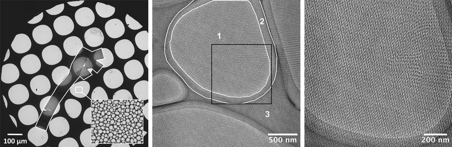
Figure 4. TEM overview images of poly(styrene)-b-poly(isoprene). Left: overview of EM grid with sections marked with a white outline. A magnified image of the microgrid within the holes is visible in the lower right corner. The mesh size of the microgrid is in the range of about 500 nm up to several micrometers. Center: Magnified image of an exemplary location with all relevant zones in the sample: 1- Sample without carbon support; 2 – Thin carbon layer; 3 – thick carbon layer. Right: Magnified image of the insert in the center image. The polymer structure becomes visible (see also Fig. 3). Image Credit: Akemi Kumagai - Institute of Multidisciplinary Research for Advanced Materials, Tohoku, Japan
Due to the blistered structure of the supporting microgrid, several distinct imaging zones can be observed depending on the position, including areas without carbon support as well as regions with thin or thick carbon layers. Higher magnification of the polymer in unsupported grid regions provides further insight into the structure (Figure 5).
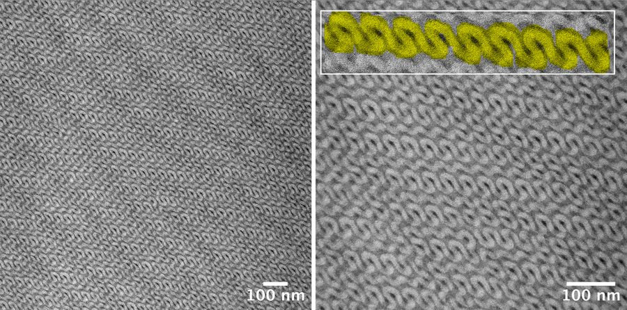
Figure 5. Magnified TEM images of 30-40 nm sections of poly(styrene)-b-poly(isoprene). Left: 40.000x magnification. Right: 80.000x magnification. The coiled structure of the polymer becomes visible. Image Credit: Akemi Kumagai - Institute of Multidisciplinary Research for Advanced Materials, Tohoku, Japan
The lamellar structure becomes clearly visible using this approach, confirming that the sections were well sectioned and appropriately collected. This also shows that it is possible to observe the fine morphology on a single section of 30-40 nm.
Figure 6 features screenshots of the three-dimensional reconstruction, further highlighting the orderly packed structure.
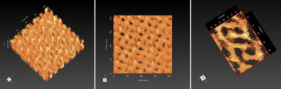
Figure 6. 3D Reconstruction of poly(styrene)-b-poly(isoprene). Left: Oblique view. Center: Top view. Right: Top view rotated. The curled, regular structure is visible. Image Credit: Akemi Kumagai - Institute of Multidisciplinary Research for Advanced Materials, Tohoku, Japan
Summary
This study evaluated the use of the UC Enuity ultramicrotome from Leica Microsystems in the preparation of polymer samples under both room temperature and cryogenic conditions.
The polymer preparation process depends on the polymer's rigidity and glass transition temperature (Tg), which determines whether cryo-sectioning is required to avoid deformation.
Room-temperature sectioning was demonstrated by embedding poly(styrene)-b-poly(methyl methacrylate) in a UV-curable resin before sectioning at 60–90 nm. The polymer’s structure was visible despite being unstained, particularly with phase contrast enhancement.
Cryo-sectioning was applied to poly(styrene)-b-poly(isoprene). Due to the limited sample volume, the material was embedded in a UV-curable resin and cooled using liquid nitrogen. Sections with a thickness of 30–40 nm were successfully obtained and analyzed by TEM, revealing well-defined lamellar structures and three-dimensional organization.
These results confirm that the UC Enuity ultramicrotome enables high-quality sample preparation for advanced polymer characterization.
Acknowledgements
Samples were provided by Prof. Hiroshi Jinnai. Sample preparation, sectioning, and imaging were carried out by Akemi Kumagai (both Institute of Multidisciplinary Research for Advanced Materials, Tohoku, Japan).

This information has been sourced, reviewed, and adapted from materials provided by Leica Microsystems GmbH.
For more information on this source, please visit Leica Microsystems GmbH.