Choosing the correct tip for a nanoindentation application is essential. KLA Instruments™ offers a range of high-precision indenter tips designed to meet the needs of demanding applications while enabling excellent research data.
This article outlines how to determine and select the best tip for a specific application.
Types of Indenter Tips
Six main types of indenter tips are available, each with a different geometry that makes it suitable for a range of applications:
- Berkovich
- Flat punch
- Vickers
- Cube-corner
- Cone
- Sphere
Berkovich Indenter Tips
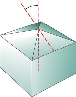
The Berkovich indenter tip (Figure 1) is the most widely employed indenter tip for measuring mechanical properties at the nanoscale via instrumented indentation testing (IIT).
This three-sided pyramid can be ground to a point, meaning that the Berkovich indenter tip maintains self-similar geometry at extremely small scales. This geometry is typically a more popular choice than the Vickers indenter tip, which is a four-sided pyramid.

Figure 1. The Berkovich indenter tip is defined as a three-sided pyramid with an included angle of 142.3 °. Image Credit: KLA Instruments™
This type of tip can be readily manufactured and is not easily damaged, making it well-suited for most testing applications. It induces plasticity at very small loads, resulting in a meaningful hardness measurement. It features an included angle of 142.3 °, minimizing the impact of friction.
Applications suitable for Berkovich indenter tips include:
- Micro-electromechanical systems (MEMS)
- Polymers (E’ > 1GPa)
- Bulk materials
- Scratch testing
- Wear testing
- In situ imaging
- Thin films
Flat Punch Indenter Tips
The flat punch indenter tip (Figure 2) is used in the measurement of yield stress-strain. This tip is defined by a truncated cone, with a range of diameter punches available to support different applications.
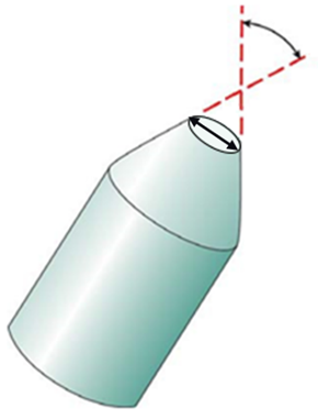
Figure 2. The flat punch indenter tip is defined by its truncated cone. Image Credit: KLA Instruments™
Applications suitable for flat punch indenter tips include:
- Stress-strain measurement
- Polymers
Vickers Indenter Tips
The Vickers indenter tip (Figure 3) is also used to measure mechanical properties on the nanoscale as part of IIT applications. This tip is defined by a four-sided pyramid.

Figure 3. The Vickers indenter tip is defined by a four-sided pyramid. Image Credit: KLA Instruments™
Applications suitable for Vickers indenter tips include:
- Films and foils
- Bulk materials
- Scratch testing
- Wear testing
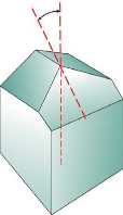
Cube-Corner Indenter Tips
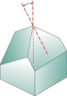
The cube-corner indenter tip (Figure 4) is a three-sided pyramid with mutually perpendicular faces arranged as the corner of a cube. This indenter’s centerline-to-face angle is 34.3 °, compared to 65.3 ° for the Berkovich indenter.
The cube corner’s sharpness produces much higher strains and stresses in the contact area, which makes it well-suited to producing very small, well-defined cracks around hardness impressions in brittle materials. It is possible to use these cracks to estimate fracture toughness at very small scales.
Applications suitable for cube-corner indenter tips include:
- Scratch testing
- Fracture toughness
- Wear testing
- Thin films
- MEMS
- In situ imaging

Figure 4. The cube-corner indenter tip is a three-sided pyramid, with a centerline-to-face angle of 34.3 °. Image Credit: KLA Instruments™
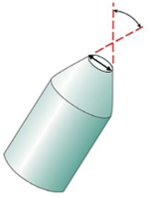
Cone Indenter Tips
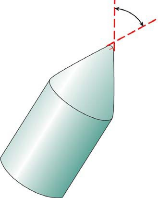
The cone indenter tip (Figure 5) features a sharp self-similar geometry. This tip’s conical symmetry makes it attractive from a modeling perspective, with many models leveraging cone indenter tips to support IIT based on conical indentation contact.

Figure 5. The cone indenter tip. Image Credit: KLA Instruments™
The cone is also an attractive option due to the absence of complications associated with stress concentrations at the indenter's sharp edges.
Very little IIT testing has been conducted with cones, however, because it is difficult to manufacture conical diamonds with sharp tips. This limitation means that cone indenter tips are of little use in the small-scale work associated with most IIT applications.
This problem does not apply at larger scales, however, where there is significant potential to leverage conical indenters in IIT experimentation.
Applications suitable for cone indenter tips include:
- Scratch testing
- Wear testing
- In situ imaging
- MEMS
Sphere Indenter Tips
Stresses develop differently during indentation when using a spherical indenter tip (Figure 6) compared with either a Berkovich or a Vickers tip.
Contact stresses are initially small for spherical indenters, producing only elastic deformation. A transition from elastic to plastic deformation occurs as the spherical indenter is driven into the surface. This can theoretically be employed to examine yielding and work hardening and to recreate an entire uniaxial stress-strain curve from data acquired in a single test.
IIT with spheres has seen the most success when employed with larger-diameter indenters. The use of spherical indenters at the micron scale has been hindered by difficulties in obtaining high-quality spheres made of hard, rigid materials.
The Berkovich indenter has been the indenter of choice for most small-scale testing because of this limitation, even though it is unsuitable for investigations of the elastic-plastic transition.
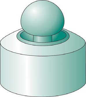
Figure 6. The sphere indenter tip. Image Credit: KLA Instruments™
Sphere indenter tips are generally used for scratch testing.
Custom Shape Indenter Tips
Standard geometry indenters may not always achieve the desired results. Applications engineers at KLA Instruments regularly work with the company’s customers to select a custom-designed indenter geometry that best suits their specific application.
Source: KLA Instruments™
| |
Berkovich |
Flat Punch |
Vickers |
Cube-Corner |
Cone
(angle ψ) |
Sphere
(radius R) |
| |
 |
 |
 |
 |
 |
 |
| Shape |
Three-sided pyramid |
Truncated
cone
(diameter 2a) |
Four-sided
pyramid |
Three-sided
pyramid with
perpendicular
faces |
Conical |
Spherical |
| Applications |
Bulk materials, thin films, polymers, scratch, wear, MEMS, imaging |
Polymers, stress-strain measurement |
Bulk materials, films and foils, scratch, wear |
Thin films, scratch, fracture toughness, wear, MEMS, imaging |
Modeling, scratch, wear, imaging, MEMS |
Scratch |
| Centerline-to-face angle, α |
65.3 ° |
- |
68 ° |
35.2644 ° |
- |
- |
| Area (projected), A(d) |
24.56 d2 |
π a2 |
24.504 d2 |
2.5981 d2 |
π a2 |
π a2 |
Volume-depth
relation, V(d) |
8.1873 d3 |
- |
8.1681 d3 |
0.8657 d3 |
- |
- |
| Projected area/face area, A/Af |
0.908 |
1.0 |
0.927 |
0.5774 |
- |
- |
| Equivalent cone angle, ψ |
70.32 ° |
- |
70.2996 ° |
42.28 ° |
- |
- |
| Contact radius, a |
- |
a |
- |
- |
d·tanψ |
(2Rd-d2)1/2 |

This information has been sourced, reviewed, and adapted from materials provided by KLA Instruments™.
For more information on this source, please visit KLA Instruments™.