Introduction The γ-TiAl alloys have gained a lot of interest in recent years. They are considered for use in aerospace applications such as aircraft, space satellites, missiles, turbine blades, engine valves and turbocharger rotors due to the high temperature strength, low density, high melting point and creep resistance at high temperatures [1-7]. The two major disadvantages for the alloys are the limited ductility at room temperature and poor surface properties at high temperature [2-5]. The limited ductility can be improved by the addition of alloying elements such as Nb, Cr, Mn, Mo, W, Ta and V [5]. The surface properties can be improved by surface modification [3, 5]. TiN coatings have been widely applied to improve hardness and wear resistance for many applications. There are many processes for coating the films. They are the physical vapor deposition (PVD) [8, 9], chemical vapor deposition (CVD) [10,11], plasma deposition [2, 12-14], cathodic arc (CA) [15-18], ion implantation [19] and direct metal-gas reaction [3,4,20]. Plasma deposition is the clean technology and is selected for this research. Experimental Alloys The alloys used for the nitridation are MJ12 and MJ47 and the compositions are listed in Table 1. They were provided by Howmet Corp. (Whitehall, MI, U.S.A.) as rods with 15.5 mm diameter and cut into the disks of 1-2 mm thick. The disks were polished down with 0.3 micron alumina powder and degreased with alcohol. Table 1. Nominal composition (at%) of the alloys | | | MJ12 | Balance | 47 | 2 | 2 | - | - | | MJ47 | Balance | 47 | 2 | - | 2 | 0.8 | Plasma System The inductively coupled plasma system used for the nitridation consists of RF power generator (Dressler model HPG 1365) discharge at 13.56 MHz in order to avoid interference from public communications [21]. The generator is connected to an antenna through a matching network and the operating power was at 150 and 250 W. The multicusp plasma chamber is made of stainless steel with 31.2 cm diameter, 42.5 cm length and 6.0 mm thickness. The external surface of the chamber is embedded with the permanent magnet buttons [22]. Nitridation The specimen was placed in the multicusp chamber. The air was evacuated to the pressure of 0.05 mtorr and argon was fed into the chamber to 0.5 mtorr. The generator was discharged at 13.56 MHz, 150 W. The –1 kV bias voltage was supplied for 7 min to clean the surface of the specimen and turned off. Then, the argon was evacuated to 0.05 mtorr and nitrogen was fed into the chamber to 0.5 mtorr. The generator was operated at 250 W and the nitridation proceeded for 1 h using the bias voltages of –3, -4, -5 and –6 kV. At the end of the process, the power of the generator, the bias voltage and the nitrogen gas were turned off. The air was fed into the chamber until the pressure was 1 atm and the specimen was brought for further analysis. Characterization By using 1 gf load and 5 s dwelling time, Knoop hardness of non-nitrided and nitrided alloys was measured ten times and the average value and the standard deviation were calculated. In addition, wear rates of the alloys were determined using a pin-on-disk wear tester. The parameters for the test are the following : | Pin | 3.175 mm radius WC ball (r) | | Load | 50 gf | | Wear track radius (R) | 4.0 mm | | Sliding velocity | 4.00 cm.s-1 | | Sliding distance | 20 m | | Lubricant | dry | | Temperature | 25oC | | Atmosphere | ambient air | The width of the wear track was measured by optical microscopy and the volume loss of the alloys was calculated using standard geometrical formulae, Disk volume loss =  where d = the width of the wear track. The volume loss per unit distance or wear rate was then determined. The nitrided alloys were analyzed using a scanning electron microscope and an energy dispersive x-ray analyzer operated at 15 kV. The nitrided alloys were analyzed using an x-ray diffractometer as well. The operating parameters were 45.0 kV, 35.0 mA and Cu-Kα as the target. Results and Discussion During the nitridation, nitrogen molecules decomposed to atoms. Some of the atoms further decomposed to ions and electrons. Some were left as atoms. The electrical charge of the ions is controlled by the power of the generator. Due to the negative voltage supplied to the specimen, the positive ions in the chamber were accelerated to the plasma-specimen interface. The energy (E) of the positive ions at the interface is E = qV Where: q = the electrical charge of the ion and V = the negative voltage. The positive ions with high energy penetrated into the alloy matrix and were resisted by the repulsive force of the host atoms on the specimen. The ions were embedded inside the matrix at some depth beneath the interface. But for the electrons, they were accelerated to the ground wall of the chamber. The surface of the specimen contains more defects and the disorder of the atoms is increased. From a thermodynamic point of view, the entropy of the system is increased. Some of the ions can form new phase(s) with the host atoms as well. The ordering of the atoms and the new phase(s) formed are able to play the role to hardness and wear resistance. The elemental spectra of nitrided MJ12 and MJ47 are shown in Figure 1. There are Ti, Al and Nb on both of the alloys. The additional Cr and Mn were detected on MJ12 and MJ47, respectively. No B was detected on MJ47 because of its light atomic mass. The results are consistent with the compositions of the alloys shown in Table 1. During the nitridation, nitrogen molecules decomposed into atoms and ions. The ions penetrated and embedded in the alloy surfaces. The additional nitrogen was detected on the two alloys. No nitrogen was detected on wear tracks showing that the deposited film is very thin. No tungsten worn from the WC ball was detected inside wear tracks showing that the concentration of the worn tungsten from the ball was very low. During the nitridation, some of nitrogen embedded in the alloy matrix and some formed new phase(s) with the alloying elements. | 
| | Figure 1. The elemental spectra of (a) MJ12 and (b) MJ47 nitrided at different bias voltages. | According to the x-ray diffraction spectra shown in Figure 2, no nitride was detected. The concentration of the nitride can be too low to be detected or the nitrogen only penetrated and embedded in the alloy matrix. The concentration of the embedded nitrogen can be too low to form nitrided phase(s) for this process. The TiAl and Al phases were detected [23] showing that the analysis was done to the depth of the metallic substrate. | 
| | Figure 2. The x-ray diffraction spectra of (a) MJ12 and (b) MJ47 nitrided at different bias voltages. | Knoop hardness of MJ12 and MJ47 shown in Figure 3 is increased with an increase in the bias voltage. It shows that the embedded nitrogen and/or nitrided phase(s) play a role in the hardness of the untreated alloys. Knoop hardness values of the untreated MJ12 and MJ47 are 464.2 ± 38.6 and 499.9 ± 63.3 kg.mm-2, respectively. At –6 kV, the highest values of the calculated hardness of MJ12 and MJ47 are 891.3 ± 51.6 and 899.8 ± 47.1 kg.mm-2, respectively. It shows that the thickness of the film is the highest and that the hardness of the alloys is successfully improved by the plasma deposition. During hardness measurement, there are some cracks generated on the brittle surfaces of the deposited films leading to the error reading of the diagonals of the indentations and the error calculating of the hardness values. | 
| | Figure 3. Knoop hardness of non-nitrided and nitrided MJ12 and MJ47. | The values of the volume loss per unit distance or wear rate are shown in Table 2. The wear rates of the nitrided MJ12 and MJ47 are greatly decreased by one or two orders of magnitude in comparison to the untreated alloys. The decrease of the wear rates was the results of the embedded nitrogen and/or nitride formation. These lead to the atomic disordering or defects on the alloy surfaces. Wear rates are also controlled by the internal stress of the film and substrate which can effect on the adhesion properties [15-17]. The decrease of the wear rates with an increase in the bias voltages is irregular due to the vibration of the WC ball during the test. This leads to the irregularity of the width of wear tracks and the calculated wear rates. The irregularity of the wear rates can be controlled by the formation of the new phases as well. Table 2. Wear rates of MJ12 and MJ47. | | | MJ12 | Non | 14.210 | | | -3 | 0.164 | | | -4 | 0.132 | | | -5 | 0.140 | | | -6 | 0.125 | | MJ47 | Non | 14.166 | | | -3 | 0.542 | | | -4 | 0.416 | | | -5 | 0.304 | | | -6 | 0.292 | During wear testing, the coefficients of friction (μ) of the alloys were recorded and the results for MJ12 are shown in Figure 4. The coefficients of friction varied with the sliding distance of the pin ball. At –3 kV nitridation, the coefficient of friction is rapidly increasing from zero to 1.00 within the first 1.0 m. Then, it showed the fluctuation around this value until at the completion of 15.5 m. At –4, –5 and –6 kV, the coefficients of friction are rapidly increasing within the very short distance to the value of 0.18 and slowly increasing until reaching the average value of 0.52. The change of the coefficients of friction was irregular due to the vibration of the pin ball, the change of the friction force and others. The results are in agreement with the wear rates as explained above. | 
| | Figure 4. Coefficients of friction of MJ12 nitrided at different bias voltages. | The relationship between the friction force (f) and the acceleration or the second derivative of the position (ü) of the WC ball is the following : f ∝ ü Friction force is not constant due to the change of its magnitude and direction. Thus, the acceleration is varied in accordance with the force. This leads to the fluctuation of the coefficient of friction. The external morphologies of the nitrided MJ12 and MJ47 are shown in Figure 5. The surface of the alloys is rather rough showing that the alloys were treated by the deposition process. The characteristics of the surface are the general nitridation and can play the role on the vibration of the WC ball leading to the fluctuation of the wear rates and the coefficient of frictions of the alloys. | 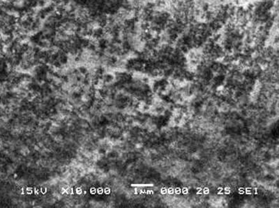
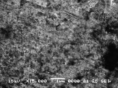
| | Figure 5. Surface morphologies of (a) MJ12 and (b) MJ47 nitrided at –6 kV bias voltage. | Conclusions The elemental analysis shows the detection of the nitrogen embedded in the alloy surface. But for the x-ray diffraction analysis, no nitride phase was detected. However, the plasma deposition can effectively improve the hardness and the wear resistance of the alloys. At bias voltage of –6 kV, the Knoop hardness values of Ti-47Al-2Nb-2Cr and Ti-47Al-2Nb-2Mn-0.8TiB2 alloys were the highest at 891.3 ± 51.6 and 899.8 ± 47.1 kg.mm-2, respectively. The wear resistance was greatly improved by one or two orders of magnitude after nitridation in comparison to the untreated alloys. The scanning electron micrographs show rather rough surfaces which can play the role on the fluctuation of the wear rates and the coefficients of friction of the alloys. Acknowledgements The research was supported by The Thailand Research Fund (TRF), Bangkok, Thailand. We are grateful to Howmet Corp., Whitehall, MI, U.S.A. for providing the alloys and to Professor Dr. T. Vilaithong, FNRF, Department of Physics, Faculty of Science, Chiang Mai University, Chiang Mai, Thailand for permission to use the plasma deposition equipment, microhardness and wear testers. References 1. R. L. Stedfeld: Director, “ASM Handbook, Properties and Selection, Nonferrous Alloys and Special-Purpose Materials, 5th Print., U.S.A.: ASM International Handbook Committee, 2 (1998) 587. 2. T. Noda, M. Okabe and S. Isobe, “Hard Surfacing of TiAl Intermetallic Compound by Plasma Carburization”, Mater. Sci. and Engin., A213 (1996) 157. 3. B. Zhao, J. Sun, J.S. Wu and Z.X. Yuan, “Gas Nitriding Behavior of TiAl Based Alloys in an Ammonia Atmosphere”, Scripta Mater., 46 (2002) 581. 4. S. Thongtem, T. Thongtem, M. J. McNallan and L.D. Yu, “Effect of High Temperature Gas Nitridation of TiAl on Wear Resistance”, J. of Mater. Process and Manufact. Sci., 6 (1998) 185. 5. W. H. Tian and M. Nemoto, “Effect of Carbon Addtion on the Microstructures and Mechanical Properties of γ-TiAl Alloys”, Intermetal., 5 (1997) 237. 6. R. Kainuma, Y. Fujita, H. Mitsui, I. Ohnuma and K. Ishida, “Phase Equilibria Among α(hcp) , β(bcc) and γ(L10) Phases in Ti-Al Base Ternary Alloys”, Intermetal., 8 (2000) 855. 7. F. Perdrix, M. F. Trichet, J. L. Bonnentien, M. Cornet and J. Bigot, “Influence of Nitrogen on the Microstructure and Mechanical Properties of Ti-48Al Alloy”, Intermetal., 9 (2001) 147. 8. J. Musil and H. Hruby, “Superhard Nanocomposite Ti1-xAlxN Films Prepared by Magnetron Sputtering”, Thin Solid Films, 365 (2000) 104. 9. S. Labdi, Ph. Houdy, P. Psyllaki and M. Jeandin, “Elaboration and Characterization of Ti and TiN Thin Films and Ti/TiN Multilayers for Hard Coating Applications”, Thin Solid Films, 275 (1996) 213. 10. S. Anderbouhr, V. Ghetta, E. Blanquet, C. Chabrol, F. Schuster, C. Bernard and R. Madar, “LPCVD and PACVD (Ti,Al)N Films : Morphology and Mechanical Properties”, Surf. and Coat. Tech., 115 (1999)103. 11. S. Gilles, N. Bourhila, S. Ikeda, C. Bernard and R. Madar, “Deposition of (Ti,Al)N Thin Films by Organometallic Chemical Vapor Deposition : Thermodynamic Prediction and Experimental Results”, Surf. and Coat. Tech., 94-95 (1997) 285. 12. J. Shieh and M. H. Hon, “Nanostructure and Hardness of Titanium Aluminum Nitride Prepared by Plasma Enhanced Chemical Vapor Deposition”, Thin Solid Films, 391 (2001) 101. 13. K. Kawata, H. Sugimura and O. Takai, “Characterization of (Ti,Al)N Films Deposited by Pulsed D.C. Plasma-Enhanced Chemical Vapor Deposition”, Thin Solid Films, 386 (2001) 271. 14. K. Kawata, H. Sugimura and O. Takai, “Characterization of Multilayer Films of Ti-Al-O-C-N System Prepared by Pulsed D.C. Plasma-Enhanced Chemical Vapor Deposition”, Thin Solid Films, 390 (2001) 64. 15. Y.Y. Guu, J.F. Lin and C.F. Ai, “The Tribological Characteristics of Titanium Nitride, Titanium Carbonitride and Titanium Carbide Coatings”, Thin Solid Films, 302 (1997) 193. 16. C. Wei, J.F. Lin, T.H. Jiang and C.F. Ai, “Tribological Characteristics of Titanium Nitride and Titanium Carbonitride Multilayer Films”, Part I, The Effect of Coating Sequence on Material and Mechanical Properties,” Thin Solid Films, 381 (2001) 94. 17. C. Wei, J. F. Lin, T.H. Jiang and C.F. Ai, “Tribological Characteristics of Titanium Nitride and Titanium Carbonitride Multilayer Films”, Part II, The Effect of Coating Sequence on Tribological Properties,” Thin Solid Films, 381 (2001) 104. 18. A. Kimura, T. Murakami, K. Yamada and T. Suzuki, “Hot-Pressed Ti-Al Targets for Synthesizing Ti1-xAlxN Films by the Arc Ion Plating Method”, Thin Solid Films, 382 (2001) 101. 19. [21[บ20 L. Xia, H. Ji, M. Sun, Y. Sun and X. Ma, “Structure and Frictional Characteristics of Ti-6Al-4V Plasma-Based Ion Implanted with Nitrogen then Acetylene”, Wear, 225-229 (1999) 835. 20. K. Matsuura and M. Kudoh, “Surface Modification of Titanium by a Diffusional Carbo-Nitriding Method”, Acta Mater., 50 (2002) 2693. 21. A. Anders, Handbook Plasma Immersion Ion Implantation and Deposition, John Wiley and Sons, NY, (2000). 22. D. Boonyawan, P. Suanpoot and T. Vilaithong, “A 13.56 MHz Multicusp Ion Source for Gaseous Ion-Beam Production”, Surf. and Coat. Tech., 112 (1999) 314. 23. Powder Diffraction File, Inorganic Phase, Search Manual(HANAWALT), Joint Committee Powder Diffraction Standards, JCPDS International Centre Diffraction Data, 1601 Park Lane, Swarthmore, PA 19081, USA, (1985). Contact Details |