Several papers have been published which attest to the fact that spectroscopy is more or less blind to the larger wear particles in an oil sample. Nevertheless, oil analysis has been shown to be extremely effective in predicting potential machine failures. It is thus not unrealistic to ask the question; “Are there benefits to additional tests such as rotrode filter spectroscopy (RFS), and will they significantly improve the probability of detecting a potential failure that may otherwise be missed by conventional analytical methods?”
The rotrode filter spectroscopy (RFS) method makes use of the fact that the carbon disc electrodes used in rotating disc electrode (RDE) spectrometers, such as the ones used in JOAP, are themselves porous. A fixture is used to clamp the discs so that oil can be drawn through the outer circumference of the discs when a vacuum is applied to the inside of the discs. The particles in the oil are captured by the disc. The oil is then washed away with solvent, the disc is allowed to dry, and the particles are left on the disc electrode so that they are vaporized and detected when run on the RDE spectrometer. A multistation fixture is used so that a number of samples can be filtered at once. The procedure is fast, and therefore economical to perform.
The rotrode filter spectroscopy (RFS) method was introduced at the previous International Condition Monitoring Conference. Since that time, a patent has been issued for the technique, and a number of systems have been fielded with the objective to enhance the capabilities oil analysis laboratories.
This paper reports on the experience to date with the RFS technique in actual machine condition monitoring applications. It will investigate the capabilities and applicability of the RFS technique as an additional test to improve the probability of detecting and identifying large wear particles that may otherwise be missed by standard spectroscopic techniques.
Introduction
Spectrometric oil analysis has been applied for more than 40 years as a routine and cost-effective condition monitoring technique. It is used to determine the elemental concentration in parts per million of wear metals, contaminants and additives in an oil sample. Commercial oil analysis laboratories report on as many as 20 different wear metals, contaminants and oil additives. With the knowledge of the wear metal and contaminant limits for the machine or engine being monitored, a determination may be made as to whether or not that equipment is operating properly.
A fact which has recently become more widely understood is that spectrometric oil analysis detection efficiency decreases as the wear particle size increases. Large particles are precisely those particles which are most indicative of an abnormal wear mode. Severe wear modes such as spalling, severe sliding wear and cutting wear generate large particles which may go undetected by spectroscopy. This is true to a greater degree for certain types of spectrometers than others. It is also more important for certain types of machines and engines.
Atomic absorption spectroscopy (AAS) and inductively coupled plasma (ICP) spectrometers suffer the most from particle detection inadequacies. Rotating disc electrode (RDE) spectrometers are responsive to somewhat larger particles, but the upper limit is still approximately 10 micrometers.
Three years ago, a new technique was introduced which demonstrates efficiency to capture large wear particles in an oil sample prior to analysis with an emission spectrometer. It has been referred to as rotrode filter spectroscopy (RFS) because it utilizes the porous disc electrode as a filter to capture wear particles. Although it appeared to enhance the particle size analysis capabilities of the rotating disc electrode (RDE) technique, its applicability to actual industrial applications was unknown.
Description of Rotrode Filter Spectroscopy
Rotrode filter spectroscopy makes use of the fact that the carbon disc electrodes used in rotating disc electrode (RDE) spectrometers are themselves porous. A fixture is used to clamp the discs so that used oil samples can be drawn through the outer circumference of the disc when a vacuum is applied to the inside of the discs, Figure 1. The particles in the oil are captured by the disc. The oil is then washed away with solvent, the disc is allowed to dry, and the particles are left on the outer circumference of the disc electrode so that they are vaporized and detected when sparked on the RDE spectrometer.
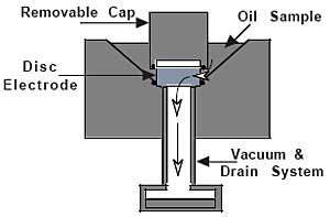
Figure 1. RFS sample preparation fixture
The disc electrode acts as a substrate for the wear and contaminant particles which become the actual sample for analysis. A pointed graphite rod is used as the counter electrode to create a spark between the electrodes resulting in the excitation of the atomic structures of any wear metals or contaminants captured by the disc electrode. The analytical procedure is identical to the analysis of a routine sample with the RDE technique. Sample preparation time of an electrode for RFS varies with the viscosity and contamination of the oil sample. Preparation time can be as short as 4 or 5 minutes for relatively clean used lubricating oil samples, such as from turbines, electric motor bearings and hydraulic systems. Engine oil samples with high soot levels require the longest filtration times, sometimes half an hour or more.
A multi-station fixture is thus used so that a number of samples can be filtered at one time, Figure 2. The procedure thus becomes economically efficient to perform.
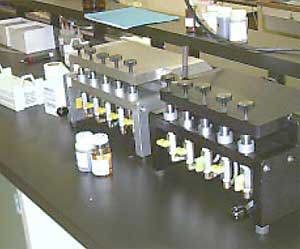
Figure 2. Multi-station RFS sample preparation fixture
The RFS technique is used as a comparative method due to the unavailability of oil standards with known gravimetric concentration of particles for each element measured by the spectrometer.
In practice, a used oil sample is first analyzed using the standard RDE technique which provides an analysis of dissolved and “fine” wear particles. A second analysis using the RFS technique detects and quantifies the larger “coarse” wear particles. The two analyses provide an indication of the wear particle size distribution in the sample. A sudden presence of large wear particles will not be seen by conventional analysis. Their presence, will however, be readily evident through the RFS analysis.
Case Histories
The RFS technique has been in use for almost two years by several commercial and one military oil analysis laboratory. The following are actual case histories based on data provided by these laboratories.
Pump Turbine Wear due to Contamination
Pump turbines are used in many parts of the world to generate electrical power. Water is pumped to an elevated reservoir at night when power is relatively inexpensive. During peak power requirement periods, the water is allowed to flow downhill to turn a turbine which is coupled to a generator. These are reliable systems. However, condition monitoring based on oil analysis can be very effective at predicting a possible failure in the very early stages of the problem and prior to secondary damage or catastrophic failure.
A pump storage system of an electric utility was part of a condition monitoring program when the laboratory, using the RFS technique, detected an increase in “coarse” wear particles in the upper guide bearing assembly of the turbine. Although the normal analysis using an emission spectrometer was acceptable, the laboratory requested more frequent sampling based on the presence of RFS data for iron and babbit metals. The original and the next three analyses using the standard, and the RFS techniques are shown in Figure 3. Although the normal emission spectrometric analysis does not show a trend, the RFS analysis definitely does.
Figure 3. Pump turbine guide bearing wear trend
Ferrographic analysis on the last two samples verified the presence of large cutting wear particles, Figure 4, causing the laboratory to issue an ALERT.
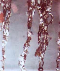
Figure 4. Ferrogram showing cutting wear and weld beads
However, the presence of spheres on the ferrogram was the eventual indicator which lead to the source of the wear problem. Tilting pad bearings such as those used on the turbine do not generate spheres in a wear mode. Weld beads were suspect and it was eventually verified that the turbine had not been protected during overhead construction work.
Weld debris including weld beads, and not a defective component, were the cause of the wear trend. Although the wear was not critical, the oil was cleaned as a precaution and more frequent oil analysis monitoring was recommended. The wear trend if undetected by the RFS technique may or may not have lead to a catastrophic failure. The thought of failure is not a pleasant one, especially in view that such a failure can require a multimillion dollar overhaul.
Bearing Wear due to Coupling Misalignment
Condition monitoring based on vibration and oil analysis has been a major focus of most modern paper mills. Many mills have large forced lubrication systems with central reservoirs that serve many bearings on rolls and drives. In this case history, the maintenance engineer suspected that a problem was occurring with a supercallender main drive motor on a specialty paper process line. Routine oil analysis with conventional methods reported no abnormalities, yet the engineer was not satisfied based on experience, preliminary vibration analysis and visual appearance of the oil sample. A decision was made to also send samples to an independent laboratory for a second opinion and analysis with the RFS technique.
Figure 5 presents the data for the next two samples. Routine spectrometric analysis is labeled as “fine” and RFS analysis is labeled as “coarse”. The first and second samples showed normal values for routine spectrometric oil analysis. Yet the RFS technique identified extremely high values for nonferrous metals. A recommendation to change the oil was made after the first sample and an ALERT condition was reported after the second.
The results show severe bearing wear to be taking place and immediate remedial action was suggested by the independent laboratory. Meanwhile, abnormal vibration data convinced the engineers that their suspicions on the cause of wear were correct, i.e. the motor was not coupled properly, and it appeared to be thrusting away from the gearbox and into both bearing thrust faces. The motor was immediately taken out of service and overhauled.
Figure 5. Fine and coarse wear particle trends for bearing wear mode
One bearing assembly, Figure 6, was replace. The motor was reinstalled and aligned, eliminating a soft foot. If the motor had remained in service, it would eventually have failed. Maintenance costs, including rewinding of the armature would have cost a minimum of $32,000 and probable production losses and delays would have increased the costs even further.
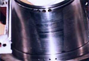
Figure 6. Damage to bearing surface due to motor misalignment
Slinger Ring Problem in Journal Bearing
The previous case histories dealt with oil analysis from plain journal bearings common to many large industrial motors and turbines. A variation of this bearing, found in high horsepower motors is the ring oiled sleeve. The rings (slingers) sit on the shaft and rotate with it, splashing oil on top of the shaft. In forced lubrication systems, these slinger rings become redundant. However, in the event of an emergency shut-down, the forced feed lubrication is lost, and these slingers act as a safety device during coast down to prevent lubricant starvation.
Slingers are generally made of clock brass or general duty bearing bronze. They are considered “soft” material compared to the carbon steel shaft. On occasion, the slinger rings can stick, causing them to wear abnormally against the rotating shaft. As this happens, they release a large amount of nonferrous copper alloy wear particles into the circulating oil.
Abnormal slinger wear was suspected in an extruder main drive motor by the predictive maintenance engineer at a large petrochemical complex. The 6,000 HP motor has a force-feed lubrication system which started to be monitored regularly through oil analysis including the RFS technique. The RFS analysis detected serious wear from the slingers, Figure 7, and it was confirmed by ferrographic analysis.
Figure 7. Wear Trend in Extruder Drive Motor
The lubrication system was placed on a monthly sampling cycle. As the wear trends increased, the oil analysis laboratory recommended an oil change based on the April 30 analysis. It was assumed that the concentration of debris within the system would be reduced, thereby minimizing the risk of damage to other components in the lubrication cycle until a detailed inspection of the bearing could be carried out at the next scheduled maintenance overhaul.
During the scheduled overhaul in October, the slingers were found to have substantial wear. The debris from the wear contributed substantially to scoring of the babbit liner on the sleeve section, Figure 8. A decision was made to reinstall the bearing, change the oil and continue monitoring on a regular monthly basis. Replacement slingers were machined in-house during the scheduled overhaul. An unscheduled shutdown and resulting disruption of the process line was avoided. The condition monitoring engineers also approached the motor manufacturer regarding design changes to reduce abnormal slinger wear.
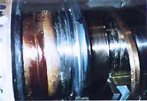
Figure 8. Slinger Ring Assembly Showing Abnormal Wear
Conclusion and Recommendations
Rotrode Filter Spectroscopy (RFS) is a new technique which has been shown in actual field applications to provide important additional information about large wear particles; information that may be missed with conventional techniques. It is applied with existing instruments with only minor procedural changes. This paper has shown how significant cost savings were achieved by utilizing the RFS technique in a standard oil analysis condition monitoring program.
In all the case histories traditional spectroscopy and the new RFS technique were sufficient to detect wear in ferrous and nonferrous parts. It was through the unique capability of RFS that coarse wear particles in both ferrous and nonferrous components were also detected. This indicator prompted further analysis techniques in order to characterize the wear mechanism(s) occurring. Additional techniques such as analytical ferrography are then applied to verify a severe wear condition. The ferrographic technique is less efficient for capture of nonferrous particles. In those samples where ferrous wear is insignificant, it is recommended that the sample be filtered through a membrane filter to capture all the nonferrous particles for subsequent microscopic examination.
The nature and particle distribution of used oil samples containing wear particles and contamination is such that the RFS technique should not be used by itself. The authors recommend that the technique is most effective when applied as an additional test in a standard oil analysis condition monitoring program. The ideal approach is to apply four techniques to screen, identify and verify the presence of fine and coarse wear particles. The four tests are:
- Atomic Emission Spectroscopy (AES) is used as a screening test to qualitatively and quantitatively identify fine and dissolved ferrous and nonferrous wear and contaminant particles. It is a rapid test which produces data for as many as twenty wear metals, contaminants and additives in less than one minute.
- Rotrode Filter Spectroscopy (RFS) is used as a second screening test to qualitatively and quantitatively identify coarse ferrous and nonferrous wear and contaminant particles. It is a relatively rapid test which identifies wear particles at sizes where the AES technique loses efficiency.
- Analytical Ferrography (AE) is an analytical test performed only when the AES or RFS techniques suggest severe wear or contamination. It involves the separation of particles from the sample for viewing with an optical microscope. It is used to identify particle size and wear modes primarily for ferrous particles.
- Millipore™ Patch Test (MPT) as an analytical test performed when the AES and RFS techniques suggest severe nonferrous wear or contamination and when analytical ferrography may not capture and display the nonferrous particles. It involves passing an oil sample through a filtering membrane for viewing with an optical microscope.
It is the combination of the information provided by these tests that leads to an effective condition monitoring maintenance recommendation. The availability of the information allows the maintenance personnel to identify a problem, locate its source and make corrective recommendation. The two years of field testing have demonstrated that the RFS techniques can be applied as an effective complimentary technique to existing oil analysis programs. There are, however, a number of remaining questions regarding the technique.
On going research is taking place to answer the following questions:
- What is the actual upper particle size capability of the technique?
- Can repeatability be improved or is it a function of the particle size distribution?
- Is it possible to use actual metal powders for calibration?

This information has been sourced, reviewed and adapted from materials provided by AMETEK Spectro Scientific.
For more information on this source, please visit AMETEK Spectro Scientific.