Microfluidics technology is gaining a lot of attention. Microfluidics devices enable the control of very small liquid quantities and have boosted several new applications in biotechnology. Such devices include wells, channels and control structures fabricated in materials such as glass, silicon or polymer (Fig. 1).
The Zeta-300 Automated 3D Metrology System helps image and analyze device features that include the following:
- See-through transparent layers to image wells.
- Measure dimensions from sub-micron to over a millimeter.
- Handle high-roughness and low-reflectivity surfaces.
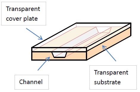
Figure 1. Schematic representation of a microfluidics device.
Vertical Dimension Analysis
The following figures show vertical dimension analysis done using the Zeta-300 Automated 3D Metrology System:
Figure 2 shows the Zeta image of a fully open channel
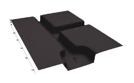
Figure 2. Zeta image of a fully open channel.
Figure 3 shows the step height analysis of the open channel.
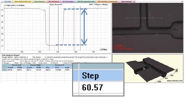
Figure 3. Step height analysis of the open channel.
Figure 4 shows the Zeta image of a channel having a transparent cover plate, showing top, middle and bottom surfaces.
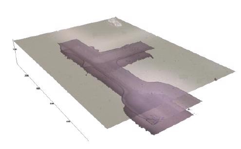
Figure 4. Zeta image of a channel with a transparent cover plate, showing top, middle and bottom surfaces.
Figure 5 shows the analysis of the multi surface image: the cover plate thickness is 93.4 μm and the channel depth is 59.2 μm.
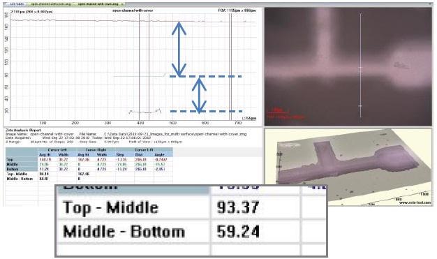
Figure 5. Analysis of the multi-surface image, showing the cover plate thickness (93.4 μm) and channel depth (59.2 μm).
Lateral Dimensional Analysis
The following figures show lateral dimension analysis performed using the Zeta-300 Automated 3D Metrology System:
Figure 6 shows the analysis of a structured microfluidic channel showing the heights of two adjacent pyramid structures.
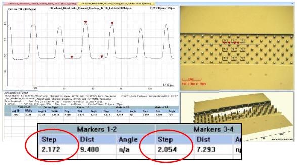
Figure 6. Analysis of a structured microfluidic channel, showing the heights of two adjacent pyramid structures.
Figure 7 shows X- and Y-dimensional analysis of an open well structure near a covered channel. The well outer, inner diameter and channel width are 505.4, 310.5 and 102.9 μm, respectively.
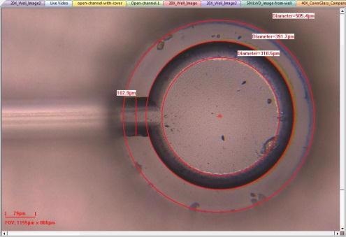
Figure 7. Analysis in the X and Y dimensions of an open well structure next to a covered channel.
The Zeta-300 System
The Zeta-300 Automated 3D Measurement System offers true color imaging of complex surfaces in less than one minute per site.
Salient Features
The features of the Zeta-300 System are:
- High-brightness white LED light source.
- XY stage with 200 x 200 mm travel.
- 30 mm total vertical travel.
- Multiple FOV configurations available.
- Intel Core2 Duo processor with 3GB RAM, 320 GB disk, and widescreen LCD monitor.
Optical Specifications
The optical specifications of the Zeta-300 system are shown in the table below:
Table 1. Optical specification of the Zeta-300 system.
| Optical Specifications |
| |
5x |
10x |
20x |
50x |
100x |
| Z res(μm) |
5.90 |
1.50 |
0.50 |
0.10 |
0.07 |
| N.A. |
0.15 |
0.30 |
0.45 |
0.80 |
0.90 |
| XY res(μm) |
2.20 |
1.10 |
0.75 |
0.42 |
0.40 |
| FOV 1(μm) |
1920x1440 |
960x720 |
480x360 |
192x144 |
96x72 |
| FOV 2(μm) |
5029x3771 |
2514x1886 |
1257x943 |
503x377 |
251x189 |
| Accuracy ± 2.5% Repeatability ≤ 1.5%(1σ/mean) |
Zeta 3D Software
Zeta 3D Software analyzes two-dimensional or three-dimensional images with respect to the following features:
- Step height.
- Surface roughness.
- Feature size, diameter, area, and volume.
- Multi-surface analysis for transparent features.
- 3D surface visualization.
- Statistics.
General Applications of Zeta-300
The Zeta-300 can be used for the following applications:
- Multi-site measurements with statistics.
- Recipe-based measurement definitions.
- Automated data and image export.
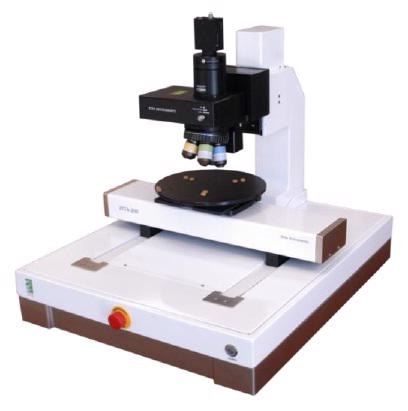
Figure 8. Zeta -300 system series.

This information has been sourced, reviewed and adapted from materials provided by KLA Corporation.
For more information on this source, please visit KLA Corporation.