|
A total knee replacement (TKR) may sound like a pretty drastic operation, but in fact it is an increasingly routine process providing relief from pain, improved leg function and improved quality of life to many thousands of people each year suffering from disorders of the knee joint.
Osteoarthritis, rheumatoid arthritis and osteoporosis in the knee can all necessitate the operation, which involves removing the articulating surfaces of the diseased joint and replacing them with artificial components.
Total knee replacements, along with total hip replacements, are highly successful operations providing an average service life of 10-15 years. The components are being continually developed with the aim of increasing the service life and improving the function, thus increasing the success of joint replacement operations in younger patients.
However, at present no standard protocol exists for testing the safety and efficacy of new knee designs prior to clinical trials.
The Department of Trade and Industry’s Characterisation of Advanced Materials programme aims to provide scientifically validated test methods, standards and codes of practise for designers and manufacturers.
These are necessary to support the quest for more complex products that meet ever more stringent specifications. The DTI has commissioned the Centre for Biomedical Engineering, University College London (UK), in collaboration with the Department of Engineering Materials, University of Southampton (UK), to develop and validate a method for testing the endurance of components in artificial knee joints.
This would allow new designs to be evaluated and their lifetimes in patients predicted with reasonable confidence.
Components of a TKR
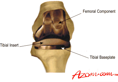
A typical TKR, figure 1, consists of a tibial baseplate (also known as a tray) with an insert that forms the bearing surface.
The femoral component articulates with the bearing surface, together with the knee cap, or patella. Depending on the condition of the natural patella it may or may not be replaced with the rest of the knee.
|

|
|
Figure 1. A typical knee replacement showing the femoral and tibial components
|
Problems with TKRs
Despite the success of such total knee replacements, complications do occur. One problem is the fracture of metallic tibial baseplates. Although this is a rare occurrence it nonetheless leads to catastrophic failure of the artificial joint and a revision operation is needed.
Possible causes of fracture include poorly positioned trays, increased loading owing to patient weight and/or activity level, tray design, and manufacturing defects and processes affecting material properties.
Bone loss, both as a response to the prosthesis or as a result of bony deformities is another factor, along with the formation of fibrous tissue between the bone and the implant's cement leading to inadequate support of the tray.
The most common fracture mechanism is thought to happen when there is insufficient bone support but the stem of the tray is fixed firmly in place. This tends to increase the load on the unsupported side of the tray and results in fracture of the component.
ISO Testing Procedure
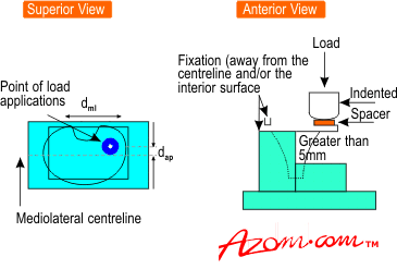
The International Standards Organisation has proposed a test to ensure that tibial trays do not fail prematurely from fatigue fracture, figure 2.
The test specimen is held as a cantilever - one half is fixed rigidly and the unsupported half is subjected to loading. The cyclic load is applied until crack formation or 5 million cycles is achieved.
The position at which the load is applied was first defined in 1996 as being relative to the mediolateral and anterioposterior centrelines of the implant component, but was redefined in 1997 as being the contact position between the femur and tibia when the knee is in its ‘neutral position’ - ie zero degrees of flexion. The ISO committee has not yet defined the magnitude of the load to be applied.
|

|
|
Figure 2. Standardised testing method for tibial trays proposed by the International Standards Organisation (draft standard 14879-1).
|
The Study
The objective of our study is to evaluate the ISO’s proposed test by analysing two components, one with a known history of failure by fracture and one that does not have such a record.
These components are the Kinematic and the Kinemax respectively, supplied by Howmedica Inc. Our study examined the performance of both components, using the two defined contact positions with a load of 2000N. This value is based on theoretical calculation of the peak force experienced by the knee during normal walking.
As only one side or ‘condyle’ of the tray is loaded in the test, we assumed that this condyle receives the total physiological load.
Finite Element Analysis
We used finite element analysis (FEA) to calculate the stresses in the two tibial tray designs when they are subjected to the conditions proposed in the ISO test. FEA predicted that both the Kinematic and Kinemax trays would fail rapidly with the load. applied to either contact position. Static tests performed on the Kinematic tray showed permanent deformation, figure 3.
Fatigue testing carried out on the Kinemax tray showed failure of the components after fewer than 375,000 cycles. However, in patients the Kinematic tray has been reported to have a failure rate of only 1‑2%. There are no published reports of Kinemax tray failure.
We have to conclude that the ISO test is unrealistic and that it exaggerates the stresses on the tibial baseplate. Using a load of 2000N, the test cannot differentiate between tibial trays that are known to fail in vivo and trays that give successful clinical performance.
Further FEA studies using a load of 5OON showed that the Kinematic would still fail owing to fatigue but that the Kinemax would survive. Two additional components that have a long history of clinical success, the AGC and 1112, also failed at 2000N but survived at a load of 5OON, figure 4.
We therefore recommend that if the ISO test is to be used then a sub-physiological load is required - in other words, a load somewhat less than that actually experienced during walking. We propose that by using a value of 5OON, the test would effectively screen between those components that are likely to fail under physiological conditions, figure 5, and those that would not.
One of the most important aspects of a standardised protocol is in ensuring that implants are rigorously tested in a valid and appropriate manner that represents the failures seen in vivo. However, our study has shown that the ISO test does not reproduce stresses experienced by a tray clinically.
Therefore, further work in this field needs to be carried out to establish more clinically-relevant support conditions for a tray in the mechanical test, so that physiological load levels can be used.
Additional Testing
In an attempt to take into account the more damaging types of physical movement experienced within the range of mobile activities, we have employed accelerated lifting techniques to test the components.
Simplified test specimens have been designed on which to carry out fatigue lifting studies. Mixed mode loading conditions (tension and shear) determined in the FEA studies and variable amplitude loading based on in vivo performance have been applied to the specimens.
The critical load excursions responsible for the fatigue fractures observed in vivo have been determined, and a truncated accelerated loading spectrum for an equivalent fatigue life is being established.
Summary
Further tests are planned to validate these accelerated lifting studies and, following consultations with the companies involved in the Industrial Advisory Group, and modifications to the ISO's draft standard (14789-1) will be proposed.
|