|
Formula one car monocoques, aircraft structural components, bridge support sections and boat hulls are all examples of structures that can be fabricated from fibre reinforced polymers such as carbon fibre/epoxy and glass polyester composites.
Another characteristic these components share is that, in service, they are normally loaded in more than one direction at once, that is, they are biaxially loaded. However, their adoption by industry at large has been slow, mainly due to the uncertainty and limitations in the understanding of how these materials behave.
It has been recognised that limiting the evaluation of a material characteristic to uniaxial coupon tests can lead to a misrepresentation of the behaviour of a material in an engineering structure. However, using more realistic loading during the test, i.e. introducing biaxial conditions, leads to a more accurate representation of the expected behaviour of the structure in-service, which could in turn lead to far wider use of composites.
Behaviour of Composites Compared to Metals
Unlike the situation with metals, the failure of composites under multi-axial loading has, until quite recently, been poorly understood.
Due to the inherently anisotropic structure of the material, its strength under biaxial conditions critically depends on how well the loads match the fibre directions in the material under test. If they are well matched the biaxial strength may exceed the value that might be expected from simple uniaxial tensile and compressive tests. Conversely, if they are poorly matched the strength can be quite low.
Biaxial Testing of Polymer Matrix Composites
Polymer composites in the form of tubes have been tested under biaxial loading conditions by QinetiQ (formerly the Defence Evaluation and Research Agency, DERA) since the mid-1970s, leading to the creation of a large body of biaxial test data backed by a theoretical understanding of the failure criteria that apply.
However, for many applications the materials are used in the form of flat or gently curved panels, so tubular test specimens are unsuitable. For this reason biaxial testing facilities for planar specimens have been developed within QinetiQ at Farnborough from 1993 onwards.
This has culminated in a family of cruciform test specimen designs that can be used to cover the complete biaxial failure envelope, that is tension-tension, tension-compression, compression-compression and all the intermediate states.
Devising Valid Testing Procedures
It has proved extremely difficult to devise a valid biaxial test for a flat coupon that would avoid premature failures at the re-entrant corners and give a large region of uniform strain at the specimen centre.
This was finally achieved using a combination of stress analysis and loading experiments, although it should be noted that the cruciform specimens require a weakening feature in the centre, to ensure a valid failure.
This is not a limitation of tube testing, which is why this has had an essential part to play in the development of biaxial failure criteria.
What Can Biaxial Testing be Used to Test?
The basic cruciform coupon test can be used to measure basic material properties and also the behaviour of specific features of interest under biaxial loading conditions.
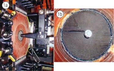
This would include open holes, holes containing fasteners, impact damage sites and loaded fasteners. This last type of test is made possible by the bolt loading facility shown in Figure 1.
Recent work has also examined the progression of fatigue damage under biaxial cyclic loading and measured the effects of through-thickness reinforcement.
|
|
|
Figure 1. Investigation of the loading of a bolt in a specimen under biaxial stress.
|
Recent Developments in Biaxial Testing
Within the last four years, it has been possible to test coupons containing three-dimensional structural features such as stiffener intersections in composite nacelle structures and composite bridge joints.
When a test piece containing such a feature is designed, some approximation has to be made to give mock joint or structure with symmetry about the mid-plane, otherwise unwanted bending stresses arise during loading. The test specimen is end tabbed and stress analysed to ensure that load is transferred correctly into the joint.
Once again, this design process involves close integration of numerical and experimental techniques, to ensure that the behaviour of the real structural feature of interest has been correctly reproduced. An obvious advantage with this approach is that the joint can be evaluated and developed while taking into account the surrounding structure and the global biaxial stress field that pertains.
This permits the development of novel joint design to occur with considerably more confidence.
Limitations of the Testing Procedure
The development of the cruciform biaxial specimen geometry, and the wealth of experience gained in testing during the last few years, has enabled many aspects of material and structural performance under biaxial loading to be assessed.
However, as with all research, when one question is answered, a multitude of other questions tends to arise. One of these is how to instrument the test specimens in order to verify the way in which the load is transferred into them and to be able to monitor any changes in the stress field that may occur as damage progresses.
While an array of strain gauges gives a series of point strains that can be used to validate a numerical model and to establish the biaxial strain field in the test region, this technique has limitations. When investigating the influence of bolt bearing, for example, there is a physical limitation on the proximity of the strain gauges to the hole.
Instrumented bolts exist, and can be used to address this latter problem by giving information on the strains on the bolt within the hole. However, unless care is taken, the instrumented bolt itself can significantly alter the bearing load on the structure, so this is often not a viable option.
Assessing the Overall Behaviour of a Test Piece
What is really required as an adjunct to biaxial testing is a global measurement technique that enables the overall behaviour of a complex test piece to be assessed. Shadow moire has been used to identify out of plane displacements around an open hole in an aircraft wing and has been successfully adapted by QinetiQ for examining the details of compression failure in biaxial tests.
However, for in-plane strain measurement, a novel technique that combines thermoelastic and photoelastic analysis, described below, and developed at the University of Sheffield, has been found to be very powerful.
Using Photoelastic and Thermoelastic Testing
The essence of the technique is that conventional photoelasticity gives the difference between the principal stresses and thermoelasticity the sum. By combining the two types of data, full separation of the two principal stresses can be carried out over the whole surface of the test specimen.
The method is ideally suited to monitoring a biaxial fatigue test, as the continuous oscillation of the load generates the necessary thermoelastic effect and subsequently enables the slow propagation of damage to be followed. The combined use of thermoelastic stress analysis and reflection photoelastic analysis had already been used for a number of applications, but this is the first time it has been applied to the direct determination of the biaxial strain state on the surface of a cruciform specimen.
Figures 2-4 show some of the photoelastic and thermoelastic data that can be obtained. The new analysis system used in this work brings together two existing stress analysis tools.
The thermoelastic system, Deltatherm 1550, is manufactured by Stress Photonics Inc, Wisconsin, while the photoelastic system, PSIOS (Phase Stepped Images Observed Simultaneously), was developed at the University of Sheffield to allow the simultaneous capture of four phase-stepped photoelastic images.
The greyscale images are combined and processed to produce full-field maps of continuous fringe order and isoclinic angle. A conventional reflection photoelastic coating was used to obtain both data sets. The two systems are mounted on a common baseplate and are aligned on the same optical path with reflective optics. The data sets obtained from this combined optical head are then calibrated and combined to produce maps of individual principal stresses.
|
|
|
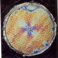
Figure 2. Photoelastic analysis of the strain field around a drilled hole in a novel material subjected to biaxial fatigue loading.
|
|
|
|
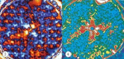
Figure 3. Thermoelastic data showing the cyclic change in the sum of the principal stresses.
Figure 4. Photoelastic data showing the continuous isochromatic fringe order.
|
Summary
Overall, it would appear that despite the large advantages that composite materials offer, in the form of greatly enhanced strength to weight and stiffness to weight ratios over metals, their adoption by industry, as mentioned at the beginning of the article, has been slow.
The use of biaxial testing represents a major step forward in understanding their properties and establishing a way forward to the next generation of advanced structures, leaving traditional ‘black aluminium’ designs in the past.
|