| Since the early days of the radiography inspection technique workers have endeavoured to obtain more detailed information from the radiographs they have produced. In radiography, when clear images of fine detail are of paramount importance, the limiting factor - the geometry of the radiographic technique - often exceeds the resolving power of the finest film. With micro-focus radiography, this geometric lack of sharpness is almost eliminated, and the technique offers greatly improved results in a broad range of applications. Bodycote Radiography’s Burton upon Trent Laboratory has recently taken delivery of a new micro-focus radiography instrument, and its performance is enabling rapid and high quality testing of numerous components and objects, for example figure 1. | 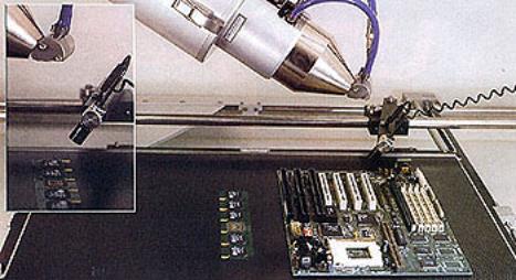
| | Figure 1. Micro-focus radiography system being used to examine a circuit board. | Key Benefit of Micro-Focus X-Radiography The sharpness of micro-focus X-radiography is its key benefit. The degree of sharpness obtained from a radiograph is determined by the focal spot size of the X-ray tube. The projection of the focal spot size on to a surface perpendicular to the axis of the X-ray beam is termed the ‘effective focal spot size’ or the ‘focus size’. This focus has to be as small as possible in order to achieve maximum sharpness in the radiographic image. The dimensions of the focus are governed by the size of the focal spot, and the value of angle, figure 2. | 
| | Figure 2. The dimensions of the focus of the inspection system are governed by the size of the focal spot and the value of the angle. | Conventional X-ray tubes offer effective focal spot sizes in the range of 4 x 4 mm down to 1 x 1 mm. There are also fine focus tubes that have focal spot sizes from 0.5 x 0.5 mm down to 50 micrometres diameter. Below this size, by convention, tubes with focal spots of 50 micrometres in diameter or less are called ‘micro-focus X-ray tubes’. Conventional vs. Micro-Focus Radiography The difference in sharpness between conventional and micro-focus X-radiography can be shown by considering the following example. A conventional X-ray tube with a 1.5 mm focal spot size, at a film-to-focus distance of 780 mm and an object-to-film distance of 20 mm would result in an ‘unsharpness’ of 0.038 mm. Using a micro-focus tube with a 15 micrometre focal spot size, the same set up would produce unsharpness of 0.00038 mm. This means that the micro-focus image can be magnified as much as 50 times, while still offering better definition than a simple shot with a conventional 1.5 mm X-ray tube. For example, at a magnification of x50 in the above set up, the geometric unsharpness using the micro-focus tube is still only 0.019 mm, half that of the conventional 1.5 mm tube with no magnification. The Film-Technique When undertaking the film technique of micro-focus X-radiography, component alignment is critical and consequently the set-up takes more time. Shot times can vary from two to fifteen minutes when using film, with additional time required for film developing. Usually the initial set-up is performed using the real-time technique. The Real-Time Method With the real-time method, the film used in conventional radiography is replaced with a fluorescent screen and an electronic intensifier that converts the X-rays into a visible image, figure 3. The part is evaluated at the same time that it is being exposed to X-rays. Individual evaluation times can range from 15 seconds to several minutes depending on the complexity of the part. | 
| | Figure 3. Using the real-time method, the film used in conventional radiography is replaced with a fluorescent screen and electronic image intensifier that converts the x-rays into a visual image. | Images and Image Enhancement Images may be enhanced and printed out as a hard copy, or may be recorded on tape or disk. Image enhancement improves image quality by averaging frames, performing edge sharpening operations, and modifying brightness and contrast. Individual frames can be grabbed live or from videotape for further analysis, or for use in presentations and reports. Applications for Micro-Focus Radiography The range of applications for micro-focus radiography is diverse and growing daily. Some of the current uses include: • Solder joint inspection on printed circuit boards, figure 1 • Die bonding and wire bonding on integrated circuits • Inspection of electromechanical components such as sensors, relays, fuses and coils etc for short circuits or missing parts, especially when the components are in the encapsulated condition • Inspection of active and passive components, electronic sub-assemblies and hybrid modules • Examination of plastics, ceramic materials, light alloys and steel for material inclusions, porosity and defects • Examination of laboratory samples in experimental medicine, biology and forensic science. Micro-Focus Radiography as a Form of Non-Destructive Testing One application that is routine practice at Bodycote Radiography,s laboratories across the UK is the non-destructive testing of highly critical parts for the aerospace, power generation and automotive industries, for which the technique has proven extremely useful. While this type of work is more the norm, other more exotoic/unusual situations have been brought to Bodycote and successfully assessed using the micro-focus radiography technique. Some of these are outlined below. Case Study 1 – Wheat Development Project However, the company is occasionally approached with problems that fall some way outside of the normal remit of non-destructive testing services, yet for which X-radiography nonetheless proves highly applicable. One such instance involved the Burton upon Trent laboratory being asked to help with a research project looking into the development of a new strain of wheat that was being designed to give higher crop yields. The conventional method used to predict crop yield from a particular strain of wheat is to grow the wheat from seed to maturity and then to break it down and count the number of grains in each ear. Instead, using the capabilities of the micro-focus radiography unit, the Burton upon Trent technicians were able to enlarge a radiographic image of the ear of wheat, without losing any definition, and so count the grains inside several weeks before the wheat had fully matured. This assisted greatly in reducing the time scale required for the project and proved such a valuable asset that the research company purchased its own micro-focus radiography unit. Case Study 2 – Safety Testing of Soft Toys Cost-effectiveness is another potential benefit of real time micro-focus radiography, a fact that was highlighted recently when Bodycote Radiography was asked to assist an importer of soft toys. The company had received a large consignment of teddy bears from overseas. During its own quality checks using a metal detector, it had discovered that a number of the bears contained metal objects. With child safety being of paramount importance, the importer was faced with the prospect of having to return the entire load, so missing the Christmas season. Bodycote Radiography was asked if it could identify any metal objects inside the bears and also suggest a quick and inexpensive method of detecting them. The answer to both questions was yes - the toys were examined using a real time micro-focus X-ray system at the Burton upon Trent site. Each bear was placed on a rotating manipulator and given a complete body scan. The results were recorded on videotape and each piece of metal identified and located inside the bear to enable a quick and simple ‘operation’ to be carried out. The end result was that the teddy bears left Burton upon Trent diagnosed and cured, and the importer was able to meet the Christmas rush. Case Study 3 - Inspection of Aero Engine Components One of the major areas in which micro-focus radiography is being used is the manufacture of aero engine turbine blades. Owing to the continuing development of blades, using increasingly exotic materials that are required to work at ever increasing temperatures and pressures, micro-focus radiography has become a valuable inspection tool. It is now normal, as part of the ‘First article inspection record’, that micro-focus radiography is carried out on critical areas. The ability of the technique to magnify images without the loss of definition has been useful in revealing the grain structure of the materials in the blades, along with micro-porosity and shrinkage that would not be detectable using conventional X-ray techniques. Conclusion In conclusion, micro-focus X-radiography is proving a valuable asset in the testing, inspection and quality control of production components, and also as a research tool in the development of new products and techniques in a range of different industries. |