Direct imaging IR optics achieve the equivalent analytical capability as the FTIR spectrometer, and the unique chemometrics algorithms for repeatable, accurate and trendable TAN/TBN and water measurements. FluidScan delivers the power of a laboratory FTIR, TAN/TBN titrator and a Karl Fischer water titrator to reliability engineers responsible for monitoring the oil condition wherever and whenever they need it.
Introduction
Mid-Infrared (Mid-IR) spectroscopy is extensively used for lubricant formulation and evaluation due to the detailed information on chemical composition offered by this technique. In recent years, it has been used as a condition monitoring tool in laboratories all over the world providing degradation information of in-service lubricants by measuring properties such as oxidation, sulfation, soot, nitration and antiwear additive depletion. It is extensively accepted for this purpose with established ASTM standards (Table 1).
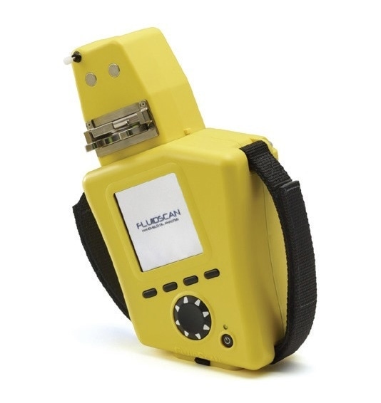
Figure 1 presents a typical infrared spectrum of an oil sample. The regions of the spectrum used for calculating typical oil condition parameters are highlighted in order to show how the IR spectrums are utilized for this purpose. Generally, such spectrums are obtained in a lab with a Fourier Transform Infrared Spectrometer (FTIR), and the analysis is carried out by a trained lab technician. Reliability professionals have not adopted FTIR spectrometers for use in the field because of the challenges of miniaturization, sample introduction and the need for high-quality, direct and actionable information without needing the operator to be a trained oil analyst.
Table 1. Quantitative parameters extracted from oil Infrared spectra and the corresponding ASTM methods and units reported.
| PROPERTY |
ASTM METHOD |
UNITS |
| Antiwear Additive |
D7412 |
abs/0.1 mm |
| Nitration |
D7624 |
abs/cm |
| Soot |
D7844 |
abs/cm |
| Sulfation |
D7415 |
abs/0.1 mm |
| Oxidation |
D7414 |
abs/0.1 mm |
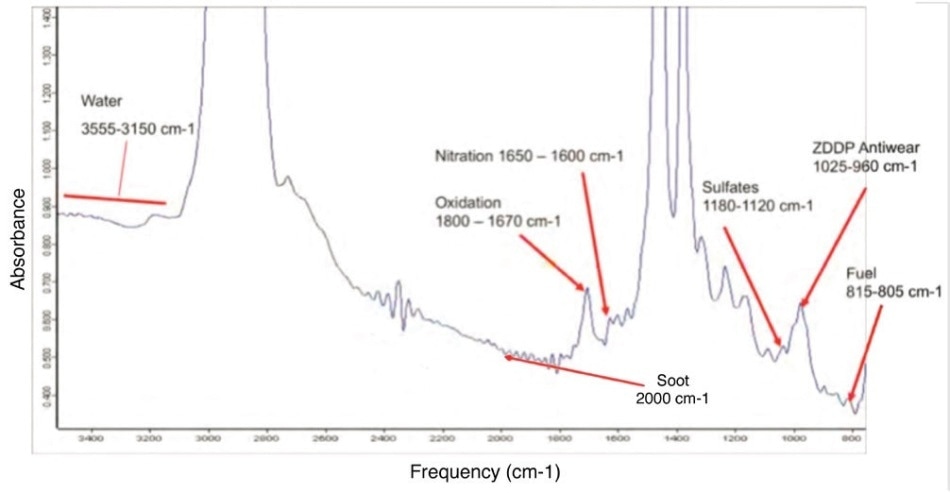
Figure 1. A typical infrared spectrum of in-service oil and parameters extracted from the spectrum. A laboratory FTIR spectrometer is a common tool to provide such information. A lab technician or data analyst then interprets the spectrum and provides quantitative information about the oil condition.
In response to the United States Department of Defense’s demand for a rugged field-based oil condition monitoring tool, Spectro Inc. developed FluidScan®, a hand-held, infrared oil analyzer that helps confirm new oil is of the proper type and free of impurities and confirms that in-service oil is fit for use, by measuring the degradation of the oil chemistry, and contamination by other liquids such as water. It is a perfect solution for condition monitoring of in-service machinery oil in critical assets such as gearboxes, turbines and compressors and for the extension of oil change intervals for engines and back-up generators [1].
FluidScan is a revolutionary device capable of combining the power of a laboratory FTIR spectrometer, a TAN/TBN Titrator and a Karl Fischer Titrator into a field-based, hand-held device, without compromising on core analyzes. Today, FluidScan is extensively accepted by the commercial and military service professionals as a perfect oil condition monitoring tool and is used for maintaining critical assets throughout the world, including mining fleets, marine vessels and power generation equipment. This article focuses on describing some of the original design considerations and how new technologies are employed in FluidScan in order to meet the design criteria.
The Design Criteria
When the Spectro design team was given the task of designing a hand-held infrared oil analyzer, a list of design criteria was established so the final device must have the following characteristics:
- Weight and size – compact for hand-held usage, battery powered
- Durability – eliminate moving parts for field use
- No solvent used in between tests in order to simplify operation in the field
- Quantitative and direct results are needed for users to make immediate decisions without the help of on-site oil experts. The list comprises of typical oil degradation and contamination parameters such as TAN, oxidation, and water contamination for industrial oils, and oxidation, sulfation, nitration, antiwear additive depletion, water, glycol, TAN, soot, etc. for engine oils.
- Battery run time for at least one shift of continuous usage
- Parameter sensitivity should be comparable to laboratory FTIR instruments
It is useful to note the difficulties in meeting all the design criteria. For instance, a new sample introduction technique was created in order to eliminate solvent usage in the field. Furthermore, much effort was put into balancing the requirement of weight and size, battery running time while guaranteeing the equivalency of analytical capability of the device to FTIR spectrometers for in-service oil analysis.
The Final Design
The final design of the FluidScan has been illustrated in Figure 2. The centerpiece is a grating dispersive optical system [2], with a solid state wave guide to decrease the light leakage and enhance signal-to-noise ratio. The optic works in 2.6 μm to 14 μm wavelength range (corresponding to ~950 to 3850 cm-1 in frequency, which covers the portion of the IR spectra indicative of degradation, TAN/TBN and water and soot). Two IR lamps are available in the system, one with a shortpass wavelength filter coupled together with a beamsplitter and one with a longpass wavelength filter. This design approach eradicates moving parts from the system with inherent durability and also removes any frequent recalibration requirements for field use.
Sample Introduction
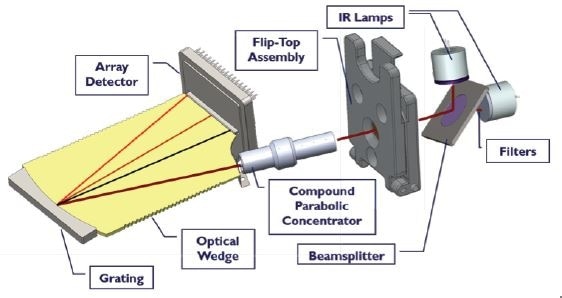
Figure 2. Schematic of FluidScan hardware, including IR source, fliptop cell and grating optics. There are no moving parts in this design.
Simple and repeatable sample introduction is vital for field-based oil analysis. A transmission cell is used and the amount of light absorbed vs. frequency passing through 100 μm of an oil sample is recorded. However, transmission cells are not ideal for field use as solvent is needed for cleaning after the sample is tested. In order to overcome this challenge, a new sample introduction technique was produced - the flip-top cell. [3]. Presented in Figure 3, it looks like a clamshell that opens for sample introduction and cleaning and closes to produce a 100 μm pathlength. The flip-top cell eradicates the need to use solvents for cleaning while maintaining same quality as a transmission cell employed in laboratory environments.
Furthermore, both ZnSe windows of the flip-top cell are wedged such that no parallel surfaces are in between the light transmission path (Figure 3). This prevents any potential optical fringes making the signal much “cleaner” than standard laboratory transmission cells. This is particularly helpful for the measurement of water, with a result that detecting 100 ppm of water in oil is possible by using infrared spectroscopy.
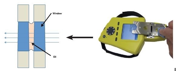
Figure 3. Fliptop cell (RHS) and schematic wedged window design (LHS).
Solving the Signal-to-Noise Ratio Challenge
In order to achieve equivalency to FTIR for in-service oil analysis, immense effort had been put into enhancing the signal-to-noise ratio of the handheld device. It is noticed that the signal-to-noise ratio of a spectrometer is proportional to the power of the source and also spectrum linewidth. In a system where the power of the source is limited, it is possible for one to increase the spectrum linewidth (decrease spectral resolution) in order to increase signal-to-noise ratio. The analogy is to extend the aperture of a camera lens in order to increase the amount of light going into the detectors.
The challenge here is to understand how much spectral resolution can be decreased without affecting the quality of the measurements. A typical FTIR spectrometer, such as Spectro Inc.’s Alpha Q410, comprises of spectrum resolution of 4 cm-1 when configured for oil analysis. Such resolution is considered to be great for new oil analysis and fingerprint identification, but it is overkill for in-service oil analysis. The question is what resolution is required for a device designed for in-service oil analysis. Parameters such as sulfation, oxidation, and soot are calculated from comparatively wide absorption peaks (Figure 1).
To determine the needed resolution, a comparison study was carried out and shown in Figure 4, where multiple FTIR scans of the same oil sample at varied spectal resolution are overlaid. Even at a resolution at 16 cm-1, there is no vital distortion in the overall heights and shape of the peaks. A detector array was then cautiously selected to balance the improvement of signal-to-noise ratio and decrease in spectral resolution to the determined level so that optimum device performance was attained. Final hardware design accounted for trade offs between S/N ratio, speed of analysis and resolution in order to optimize the performance of the FluidScan.
In order to demonstrate the performance of the final device, Figures 5a and 5b display the comparison of oxidative by-product measurements on FluidScan and a laboratory FTIR. Despite the fact that the spectral resolution on FluidScan is not as good as the FTIR spectrometer, the signature of oxidative by-products are obviously identifiable on FluidScan and the changes of the features as oil degrades also correlates extremely well with those of FTIR. Figure 7 displays how the differential ICP results (large particles) for samples E and F compare to the XRF data for the same samples. It should be noted that the XRF data is not presented in Table 1 above. The large particle portion correlates extremely well (within 3 ppm) of the filtered XRF results (Figure 7).
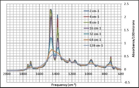
Figure 4. Overlay of oil FTIR spectra at different resolutions.
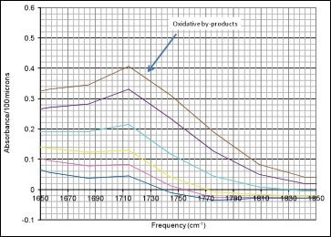
5 (a) FluidScan spectrum.
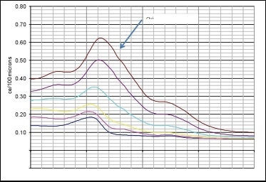
5 (b) FTIR spectrum
Figure 5. IR spectrum of degraded oil in the oxidation region. Even though the FluidScan spectrum lacks the fine details of an FTIR spectrum, it clearly shows the correlation of oil degradation to FTIR data. Furthermore, the calculated Oxidation parameter correlates well between the results from the two instruments
Correlation Study of Oil Degradation Measurement with FluidScan and Laboratory FTIR Instrument
Over the years, several inter-laboratory studies have been carried out in order to demonstrate the correlation and equivalency of FluidScan results to that of FTIR spectrometers. In one study, a random set of 37 in-service oil samples were chosen with different status and different characteristics in order to represent the real-world use case. Samples were forcefully shaken before testing. All tests were performed by a single operator on a single instrument. The FTIR tests were carried out according to the instructions of the individual ASTM test methods with measurement units as listed in Table 1.
Figure 6 a, b, c, d, e presents the correlation results between FluidScan and FTIR spectrometer for Oxidation, Nitration, Sulfation, Soot and Antiwear Additives. Additional rigorous statistical analysis according to ASTM D6708 “Standard Practice for Statistical Assessment and Improvement of Expected Agreement between Two Test Methods that Purport to Measure the Same Property of a Material” were carried out on the results. The conclusion was that the FTIR and FluidScan measurements are equivalent. In addition, based on ASTM Interlaboratory Crosscheck Program round robins for in-service oils, differences observed from FTIR to FTIR are as large as or larger than differences observed on FluidScan to FTIR as reported in this study.
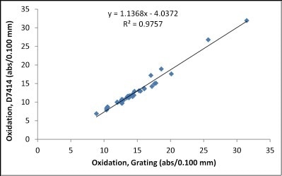
(6a): Correlation between FluidScan and ASTM D7414 for Oxidation.
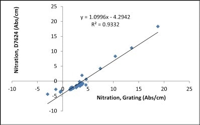
(6b): Correlation between FluidScan and ASTM D7624 for Nitration.
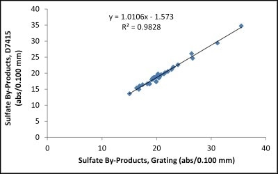
(6c): Correlation between FluidScan and ASTM D7415 for Sulfation.
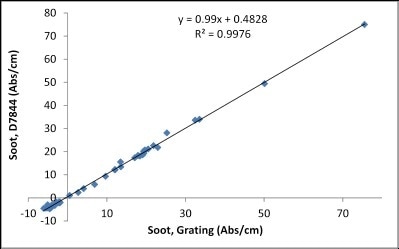
(6d): Correlation between FluidScan and ASTM D7844 for Soot.
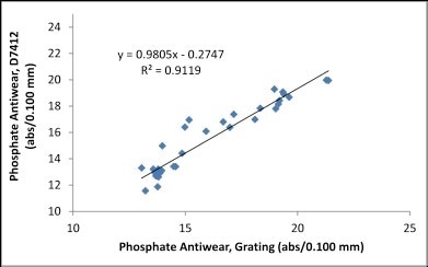
(6e): Correlation between FluidScan and ASTM D7412 for antiwear additive.
Figure 6. Correlation between FluidScan and FTIR-based ASTM methods.
Chemometrics for TAN/TBN and Water Measurement in FluidScan
One key challenge in addition to the hardware design was to provide credible results on TAN or water measurements and TBN measurements, which is difficult using IR spectroscopy. One reason is that all oils are not produced equal and if only one generic algorithm is applied to all oil, the results might be good for some oil but not for all others. If an oil-specific algorithm is produced, then it is a “mission impossible” to include all kinds of oils used all over the world. To overcome the challenge, a classifier is launched in order to classify oils into varied families. All oils share chemical similarities within a family, hence one algorithm set can be applied. With this in place on FluidScan, users in the field can rapidly match an unknown oil to a family and use a fine-tuned algorithm for parameter extraction.
Chemometrics are applied to FluidScan to obtain information on TAN/TBN and water as those provided by laboratory titration methods. Chemometrics is the application of mathematical, graphical, statistical or symbolic methods in order to maximize the chemical information extracted from data. Chemometrics uses statistical and mathematical methods to enhance the understanding of chemical information, offering spectroscopists with effective ways for solving the calibration problem for the of spectral data.
One example of chemometric calibrations for TAN of gas turbine oil has been described here. As documented in ASTM E2412, infrared signatures relating to TAN in gas turbine oils comprise of interferences from water contamination. To attain quantitative readings with the FluidScan, a chemometric calibration employing principal components regression (PCR) is used for automatically subtracting the effects of the presence in water from the TAN area of the spectrum. This process involves the following steps:
- Gather FluidScan spectra from an extensive range of used samples.
- Gather corresponding laboratory TAN and water readings.
- Choose the spectral region of interest where the property has the highest correlation (e.g. 3180 to 3750 cm-1 for TAN).
- Perform principal components regression on the spectral region with the corresponding laboratory readings.
- Assign the algorithm to a specific oil family so the same algorithm can be applied to oils with similar oils.
- Oil specific offset and slope can be modified individually for each oil in order to allow better correlation to laboratory titration methods.
This process generates a chemometric calibration which, when convoluted with an unknown spectra of turbine oil, yields the property of interest (for example, TAN) in the units of interest (mgKOH/g). A similar process has been used for water measurement in order to correlate to Karl Fischer Titration as well [3,4].
For additional information on the use of FluidScan for water measurements and TAN/TBN measurements, one can see the Spectro white papers “Measuring Water with FluidScan Fluid Condition Monitor” and “Using IR Spectroscopy for the Determination of TAN and TBN in Machinery Lubrication Oils”.
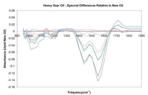
Figure 7a. Spectral evolution of a heavy gear oil relative to the new fluid, which shows both increasing and decreasing absorbances at various frequencies as the oil becomes more degraded.
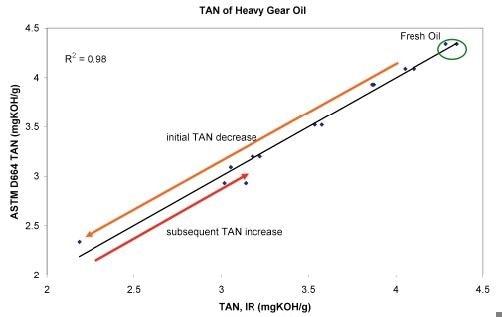
Figure 7b. Relationship between ASTM D664 and infrared TAN values for a heavy gear oil. This oil has a complicated evolution where the fresh oil’s TAN initially decreases down to a minimum level, then begins to increase towards a maximum alarm value.
Figures 7a and 7b demonstrate examples of the power of such chemometrics. As seen above, (plotted as a difference spectrum relative to the clean oil), the absorbance in the 1400-1600 cm-1 area reduces to a minimum level, steady with the depletion of an additive package in the oil. The adjacent areas begin to display an increase in absorbance that grows stronger as the TAN begins to increase from its minimum value of roughly 2 mgKOH/g (from a clean oil value of 4 mgKOH/g), up to a value of 3 mgKOH/g in this dataset. The upper TAN limit is in the range of 5 mgKOH/g. Figure 7b demonstrates that the infrared TAN has exceptional correlation to the ASTM D664- determined TAN, signifying the infrared-based chemometric analysis is able to account for and properly weight the different spectral effects observed.
Summary
FluidScan, despite being small, is packed with innovations that supply laboratory quality measurement to on-site oil analysis instruments. The patented flip-top cell offers easy-to-use, solvent-free sample introduction. Direct imaging IR optics attain the equivalent analytical capability as the FTIR spectrometer, and the unique chemometrics algorithms for repeatable, accurate and trendable TAN/TBN and water measurements. FluidScan delivers the power of a laboratory FTIR, Karl Fischer water titrator and a TAN/TBN titrator to reliability engineers who monitor the oil condition wherever and whenever they need it.
References
[1]: Spectro white paper: “Overview of FluidScan Handheld Oil Analyzer”.
[2]: US Patent, “Array detector coupled spectroanalytical system and graded blaze angle grating” US 7,495,761.
[3]: US patent, “Spectrometer flip top sample head” US 8,384,895.
[4]: Spectro white paper; “Using Infrared Spectroscopy for the Determination of TAN and TBN in Machinery Lubrication Oils”.

This information has been sourced, reviewed and adapted from materials provided by AMETEK Spectro Scientific.
For more information on this source, please visit AMETEK Spectro Scientific.