The combination of catalysis and plasmas under moderate temperatures is a developing area. Plasmas can be generated by several methods and can initiate chemical reactions either in the gas phase or at the surface of the material. There are typically two ways in which the techniques are combined. The first technique is In Plasma Catalysis (IPC) which places the catalyst into the plasma discharge. In the second technique, the catalyst is placed downstream of the discharge zone, Post Plasma Catalysis (PPC).
The introduction of a plasma to a catalysis system may create a modification in the type or distribution of reactive species available for reaction or a change of catalyst characteristics, such as a modification in catalyst structure or an increase in dispersion. In this article, a micro-reactor has been built that allows the study of catalysis using conventional temperature-programed techniques. The reactor also allows a dielectric barrier discharge (DBD) to be produced over the entire length of the catalyst region or to precede it. The DBD produces the catalyst’s surface modifications and generates a cool plasma at atmospheric pressure. It is also a source of radicals and ions which could be used in the reaction process. Test reactions have been studied to show the differences in reaction product distributions and activation temperatures when compared with the catalyst alone.
The reactor has also enabled the catalysts to be retained in the plasma in an attempt to alter the surface of the catalyst before testing them in a more traditional microreactor system.
Atmospheric-Pressure Plasma Reactors
A variety of electrical plasmas may be conducted at atmospheric pressure and the range of applications of plasmas in areas such as surface modification, waste gas treatment, and chemical synthesis is developing swiftly.
Sources of plasma designed around discharges that are produced over the surface of a dielectric covering one of the discharge electrodes, “dielectric surface barrier discharges”, are versatile examples. Generally, the plasma is acquired using a high-frequency source to produce a discharge in a flow of helium to which two or more reactant gases are added. The plasma is made up of electrons with energies up to 25 eV and near-thermal, excited, and ionized gas species.
Experiment
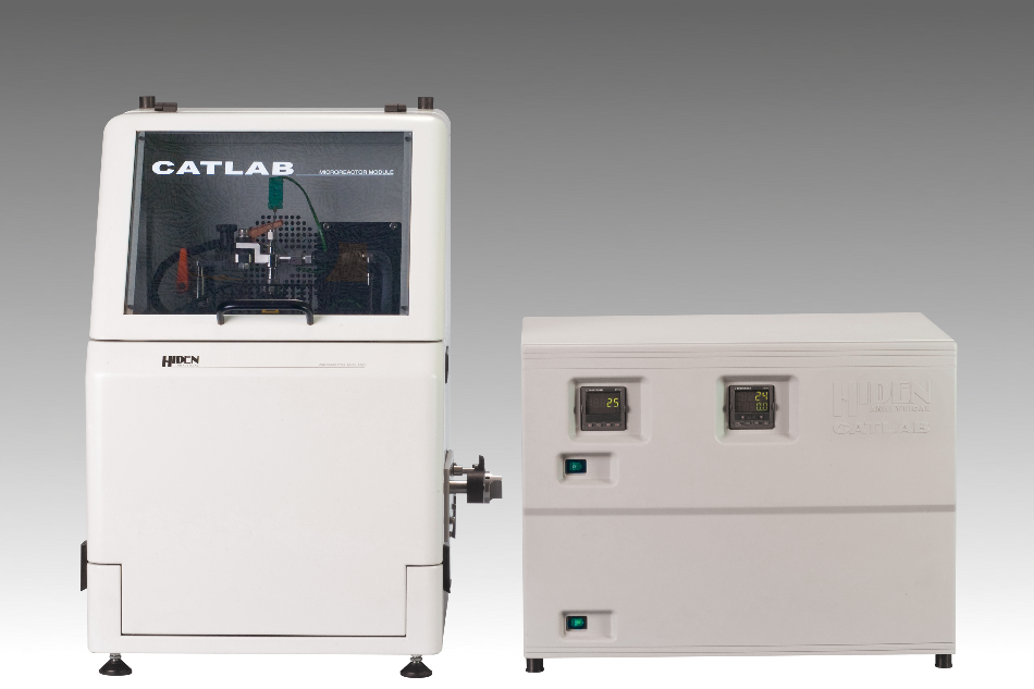
A microreactor based on the Hiden CATLAB furnace was built to permit a catalyst to be heated under controllable temperature and gas flow conditions. The microreactor was connected to the Hiden QGA capillary inlet gas analysis system. In addition to the conventional furnace arrangement, a DBD could also be produced in an area before the catalyst or over the length of the catalyst. The DBD has an inner coaxial tungsten wire electrode which is 1.0 mm in diameter and has an outer cylindrical metallic electrode enclosing the quartz tube and connected to the ground. The tungsten electrode is connected to the open-circuit end of the secondary winding of a high voltage transformer which is made to operate at 50 kHz.
Initial reactions were carried out using 1% Pd/Al2O3 catalyst. The oxidation of CO to form CO2 was the test reaction used. Using a test catalyst of Ni/MgO, plasma modified catalysts were also examined. The Ni/MgO was detained in the plasma reactor under a flow of He for 1 hour. Consequently, the Ni sample was characterized using TPR/TPD measurements that were obtained using the Hiden CATLAB microreactor system. Figure 1 shows a schematic of the plasma reactor setup.
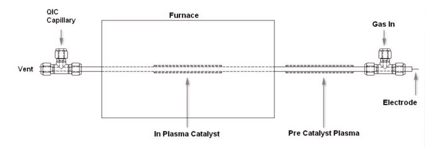
Figure 1. Schematic of Plasma Reactor.
Results – Plasma Reaction Testing
Blank experiments (no plasma, no catalyst, not shown) were conducted and showed that no reaction takes place below 500 °C.
The results of using the plasma only to initiate oxidation of CO are shown in Figure 2. When the plasma was switched on, some conversion of CO to CO2 occurred instantly as depicted in the figure.
Figure 3 represents the results of using the catalyst only. The sample was elevated from 15 °C/minute to 600 °C. The figure outlines that complete conversion of CO to CO2 took place at around 250 °C.
The plot laid out in Figure 4 is the aftermath of a combined heating and plasma experiment. Here, the plasma was generated over the length of the catalyst (IPC). The plasma was switched on before heating commenced. An initial increase in CO2 production is seen at this point. Upon heating, it can be seen that complete conversion of CO to CO2 takes place at 150 °C, 100 °C below the temperature at which reaction takes place with the temperature and catalyst alone.
In a separate experiment, the plasma was produced pre the catalyst bed (PPC). Switching on of the plasma showed a similar initial increase in CO2 production. Upon heating, it was observed that there is complete conversion of CO to CO2 at 150 °C. This is identical to the results seen with the plasma produced over the length of the catalyst. This indicates that the decrease in reaction temperature is due to the ionized gas species generated in the plasma being more reactive over the catalyst and not due to any change to the catalyst surface by the plasma being accountable for the decrease in reaction temperature.
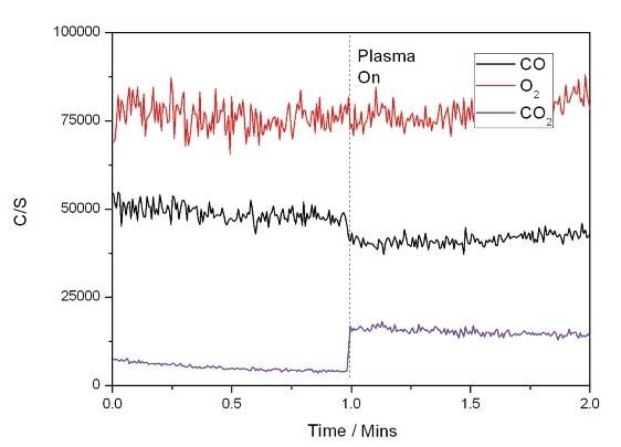
Figure 2. Plasma Only Reaction.

Figure 3. Catalyst Only Reaction.
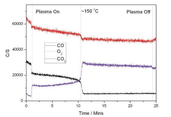
Figure 4. Plasma + Catalyst Reaction.
Results – Plasma Modified Catalysts
Characterisation of the Ni catalysts was carried out using temperature programmed reduction/desorption (TPR/TPD) experiments. TPR experiments of the unmodified and modified catalysts are shown in Figure 5. Figure 5 also shows clear differences in the TPR profiles with the altered catalyst possessing a significantly low-temperature reduction peak not seen in the unaltered sample. This difference in the reduction profile indicates that some alteration of the Ni particles has occurred using the plasma system.
The H2 TPD profiles represented in Figure 6 also show major differences between the modified and unmodified samples. The unmodified samples show at least 3 H2 desorption peaks. The modified sample displays a similar number of peaks. However, one of the peaks Tmax 190 °C is of significantly higher intensity. This signifies that the plasma modified Ni sample has a distinctive morphology of Ni particles compared with the unmodified sample. The differing intensities would also convey that an increment in Ni dispersion has occurred.
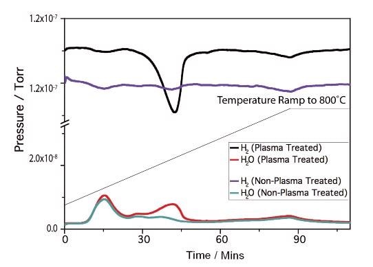
Figure 5. Ni/MgO TP.
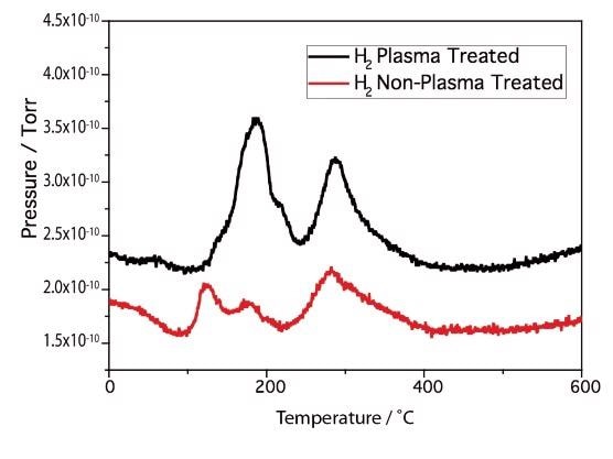
Figure 6. Ni/MgO H2 TP.
Conclusions
In the model reactor discussed in this article, oxygen and carbon monoxide are used as the reactant gases. The reactive species generated in the plasma include atomic oxygen and ions such as CO+, O+, O2+, CO2+, O–, O2–, and CO3– (The characterisation of these species could be performed using the Hiden HPR-60 molecular beam inlet system with Hiden EQP mass and energy analyser). These species combine to give carbon dioxide as the major reactor product. The conversion of CO into CO2 using a combination of catalysis and plasma is of apparent interest, as are potential improvements in the efficiency of the process through control of the plasma conditions. The overall efficiency of the conversion can also be increased considerably by exploiting the synergy between catalysts and plasmas.
The TPR/TPD results show the potential for modifying Ni catalysts using a dielectric barrier discharge plasma. Further work is needed to examine changes in reactivity of the modified plasmas.

This information has been sourced, reviewed and adapted from materials provided by Hiden Analytical.
For more information on this source, please visit Hiden Analytical.