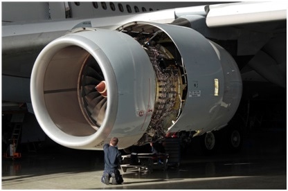
Throughout both the commercial and military aviation industry, jet engine vibration is an everyday concern, as maintenance, repair, and overhaul crews worldwide are responsible with monitoring aircraft engine vibration to ensure flight safety and efficient service.
Overall gas turbine engine vibration, however, is instead the summation of vibration contributions from a variety of moving parts within the engine. Maintenance engineers utilize vibration analysis and trim balancing tools to correlate vibration magnitude with origins from specific engine components, which provide engineers with individual sources of the vibration within an engine.
An Advanced Turbine Vibration Analyzer/Balancing System
A modern turbine engine typically contains two or three concentric shafts, which are otherwise referred to as ‘spools,’ that contain compressors, fans, and turbines. Spools are aerodynamically coupled to ensure that they turn at a variable rate. Each spool therefore contains tachometer that ensures that the rotational velocity and spool rotational angle can be measured.
Vibration sensors can also be affixed to one or more positions on the engine case to measure the magnitude of the physical shaking. These built-in tachometer and vibration sensors provide a method to measure the speed and vibration that occurs while the engine operates. Since these signals are often extremely noisy, it is not a difficult task to reliable detect their amplitude. However, it should be noted that different engines feature different signal types.
The MTI Instruments PBS-4100, which is available in two different models, is a turbine vibration analyzer/ balancing system that is useful for all engines. The test cell version (PBS-4100R+) is designed for use in a production or overhaul facility, whereas the lightweight system (PBS-4100+) is used on the ground for installed engines. Both systems are equipped with a proprietary tachometer signal conditioning technology as well as a similar principle of operation.
How It Works
The PBS-4100 Turbine Vibration Analyzer/Balancing System provides users with the ability to check the vibration amplitude of an engine, as well as balance that engine if necessary through a series of on-board digitizers that are designed to accurately measure the rotational speed of each spool, as well as the magnitude of the vibration. Embedded logic assesses the 12 o’clock position of each engine spool to further determine the exact location of an imbalance within the spool.
A series of configurable “tracking filters,” which are specialized computer algorithms that measure the rotational speed of a given spool and then filter the vibration content outside of a narrow band of interest, correlate the vibration to the spools. The narrow band of interest is the characteristic frequency of the vibration that surrounds the rotational speed of each spool. By utilizing the tracking filter for each speed, the contribution of the vibration of each spool can be separated. Any variances in the vibration as a result of engine speed, can be measured, in which the acquired data is then stored and presented in vibration versus speed trend plots.
Conduct a Turbine Engine Vibration Survey
To test the vibration within an engine, the operator will execute a vibration survey on the turbine engine that is essentially a slow cycling of the speed of the engine from idle to maximum, then back down to idle again. During this process, the PBS-4100 measures the vibration contribution from each of spool and records its findings on a series of plots. The overall vibration of the engine is also plotted during this process. The PBS-4100 notifies the user if the pre-defined limits of vibration of the engine are reached.
At the end of the vibration survey, the vibration profile is summarized for comparison against the OEM recommendations. If the vibration of any given spool exceeds an allowable limit, offset weights can be added to the engine to return balance to the spool in a similar way in which an auto mechanic adds lead weights onto an imbalanced tire.
Since the vibration magnitude and the angular position are known on the spool, a solution may be calculated by utilizing a series of highly evolved algorithms within the PBS-4100 that can potentially add one or more precisely defined weights onto designated locations/angular positions on the spool.
Quick to Configure, Easy to Use
Prior to its initial use, the user of the PBS-4100 is asked to identify the engine type and any traceability information such as its identification number, which is then followed by the system’s retrieval of the necessary operating characteristics and setup of the engine. By providing information on the balance solution to the user, they are able to better operate and execute an engine vibration survey. guidance to the operator to execute an engine vibration survey.
It is imperative that the vibration and balancing system is able to recognize the engine speed and phase of vibration of a given engine to allow the technician to determine the accurate location in which the balance weights should be added on an engine.
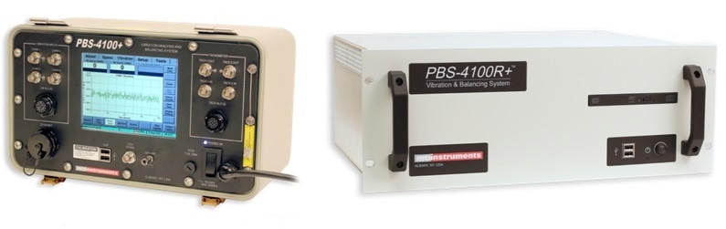
The MTI PBS-4100+ Model (left) and the PBS-4100R+ Model (right).
The TSC-4800A: A Modern Signal Conditioner for All Engine Types
Although some aircraft engine MROs do not require the acquisition of vibration data and balancing, the tachometer signal conditioning functionality is still required. In these situations, MTI’s TSC-4800A signal conditioning unit is an ideal solution, as the tachometer conditioning technology of this system is the same as that which is used in the PBS-4100. As with the PBS-4100, the TSC-4800A can accommodate all engine speed signals.
Additionally, the TSC-4800A allows the user to test engines with a long tooth or short tooth that is embedded in the N1 signal, such as engines with older high-voltage tachometer generators or engines with the new offset tooth design. The TSC-4800A can also be configured to condition as many as three individual speed signals by assigning either Channel A, B or C can to a different engine speed signal and individually controlling and programming each channel to condition different types of speed signals. Since many engines have primary and secondary speed signals, the TSC-4800A also offers multiple input sources for each channel.
In conclusion, MTI’s TSC-4800A provides useful output signals from all types of inputs, in which pulses coincident with the input signal, pulses coincident with the 1/revolution signal and raw analog signals are proportional to the input signal. The TSC-4800A can also condition signals from engine FADEC systems or other instrumentation. These signals can be square wave signals, triangle waves and short-duration pulse type signals that are produced by either magnetic, optical or laser sensors.
Advanced Signal Processing of the TSC-4800A
Each channel of the TSC-4800A utilizes a dedicated high-speed signal processor that independently samples speed signals 20 million times per second to ensure the highest accuracy and performance of the system. This processor therefore allows the TSC-4800A to reliably detect critical amplitude and timing changes in the speed signal, maintain accurate phasing of the output pulses, as well as track rapid speed changes of the engine.
Ethernet Control Interface
The TSC-4800A features a full Ethernet control interface that allows for the configuration, control and testing of the unit. This web style interface provides users with easy access to the unit from any computer that runs on an Internet browser program. This system also allows other computers to directly control the TSC-4800A using a simple, yet complete machine interface language.
Additional features that further enhance the TSC-4800A user experience include:
- Pre-defined conditioner settings that allow for rapid configuration
- An automatic power-up self test to ensure reliable operation of the system
- Firmware based design to allow for easy upgrades
- Optional Buffered Output card to provide the user with an additional 20 output signals for each input channel
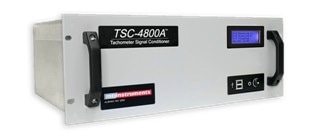
MTI’s TSC-4800A.
The Future of Portability in Jet Engine Testing
The early and rapid analysis of turbine vibration can identify problems quickly and therefore save users a significant amount of time and money that is often associated with the removal of jet engines. However, it is important to realize that the implementation of these types of troubleshooting techniques can be difficult to achieve, as mechanical constraints under the engine cowls combined with the complexity associated with the design of aircraft wiring harnesses can make the installation of accelerometers, charge amplifiers and cables a time consuming and error-prone process.
MTI’s PBS-4100+ is a portable vibration analysis and engine trim balance instrument that connects directly to the engine’s built-in sensors to read necessary signals. Coupled with aircraft-specific accessory kits (AVM Systems), this instrument simplifies balancing and vibration testing for almost any jet engine.
Similar to the larger test cell version, the portable PBS-4100+ utilizes a series of on-board digitizers and configurable tracking filters that allow the operator to simultaneously executes a similar vibration survey on the turbine engine, a plot of the measurement data on the vibration contribution from each spool, as well as the overall vibration of the engine.
As compared to current testing procedures, the portable PBS-4100+ vibration analysis and engine trim balance instrument is quick to configure and easy to use. The system is compatible with engines from all major manufacturers including GE, Pratt & Whitney, Rolls-Royce and Honeywell.

This information has been sourced, reviewed and adapted from materials provided by MTI Instruments Inc.
For more information on this source, please visit MTI Instruments Inc.