Measuring electromagnetic radiation is a crucial aspect of the development of new lighting applications like LEDs and newer generations of organic light emitting diodes (OLEDs). This can be delivered using radiometry or photometry.
Image Credit: Ekaphon maneechot/Shutterstock.com
Radiometric techniques are an unambiguous scientific method aimed at gauging the distribution of the radiation's energy in space. Radiometric methods are markedly different from photometric techniques, which considers in what way radiation can be seen by humans, i.e. according to how the sensitivity of the human eye fluctuates with wavelength.
Irradiance is the strength of light, which is measured in watts per square meter. For example, light sources that have an irradiance of one Watt/m² at a set distance of green light, are perceived by the human eye as considerably brighter than the same light with an irradiance of one Watt/m² of blue or red light viewed at the same set distance. Knowing this, radiometry can be used to deliver an accurate assessment of light sources.
Which Measurements are Radiometric?
Radiometry is the discipline of measuring levels of optical radiation in an area of the electromagnetic spectrum. It tends to be confined to the measurement of infrared, visible, and ultraviolet light using specially calibrated optical apparatus.
Using radiometry to describe a light source can be complex. It requires angular, spatial, and spectral and temporal dimensions. When using radiometry it is best to use a few specific geometric and spectral concepts by simplifying the possible requirements first.
Any light sensitive device that is able to produce a measurable output can be used as a radiometer, they normally produce changes in their temperature (measured electrically) or electrical properties (current, voltage or resistance). In most cases, the output of the detector is linked to a calibrated standard to show the amount of light absorbed by the detector accurately.
Radiometry is concerned with the radiative power exiting a light source and hitting a surface i.e., radiant emittance (outward) and irradiance or incident radiation.
Geometry and Spectral Factors Considered
When gauging the radiometry of a radiant source the geometric and spectral aspects of the system have to be taken into account. Not only are we considering the power of the radiation (light) being emitted or taken in but also where it impacts on a surface and its direction.
If a light source is emitting from a (diffuse) surface, the angle of the light emitted would have to be taken into account. Surfaces of these types are ‘Lambert emitters’ because they obey the Lambert cosine law regarding their angle of light emission.
Other light sources could be straight from a point source such as a gas discharge, these emit in every direction. In cases such as these, the radiation emitted in three dimensions takes on an angular range in two dimensions. This demonstrates the concept of the solid angle, it is equal to a circular area on the unit sphere (you are converting a cone into an angle). Such calculations allow the dimension and area of the light energy to be equated to provide reproducible measurements.
Common Geometric Descriptions
The standard geometric descriptions in radiometry are defined as flux, irradiance, radiant intensity and radiance.
- Flux (Watts) is the full optical power emitted from a source in all directions. Flux can be measured in radiometry with an Ulbricht or integrating sphere. The total amount of light discharged from something such as a light bulb is known as its flux. It is a sphere and its size depends on the power and proportions of the light source. It has an internal diffuse white coating with a spectrometer and the point light source within, which measures by indirect reflectance the total flux/power of the light source.
- Irradiance (Watts/m2): This is the flux impinging on a surface per unit of surface area.
- Radiant intensity (Watts/sr): Small radiant objects can be treated in radiometry as point sources. For these types of objects, the flux released per unit solid angle is called the intensity (sr =Steradian). Thus, intensity could be seen as the capability of a penlight to provide light onto a faraway target.
- Radiance (Watts/m2/sr): For bigger radiant sources this is the flux emitted per unit projected area per unit solid angle, this amount is the radiance. Similar to intensity, radiance can fluctuate with the direction from the object to the viewer. Any object with continuous radiance in all directions is labeled Lambertian. Typical examples of Lambertian objects are the surface of a fluorescent light tube and a highly matte sheet of paper.
Geometries can also be demonstrated in their spectroradiometric equivalent. For example, the spectroradiometric flux (Watts/nm): In this measurement, the spectrum of a light source is defined by its spectral density, in units of power per wavelength. This can also be determined in units of power per frequency.
Measurements like this can also be used to gauge the luminous flux (in lumens) and associate with the response of the human eye. Spectral irradiance, spectral radiant intensity and spectral radiance are similar to their radiometric equivalents, only providing all measurement data per wavelength.
Lighting Industry and Radiometric Measurements
In the lighting industry, new light sources such as LEDs and OLEDs are currently being studied. In current LEDs, heating effects have made measurements extremely important. This is because the heat has a direct effect on the spectral power distribution (SPD) of the LEDs and in turn the color output. In these types of studies, the total flux and SPD from a source are normally measured in an integrating sphere. The sphere and radiometer system are usually calibrated using a recognized reference source of known output flux.
When setting up a lighting system, researchers must be aware of the circumstances. When a diffuse, homogeneous lit illuminated surface is calculated, a (collimating) lens can suitably measure the light source’s properties. However, if the irradiance is coming from a large source, like a skylight or room light, a diffuser like a cosine corrector or integrating sphere in irradiance mode could be needed in front of the detector. Detectors like the Rhea and Hera are calibrated to read directly in units of irradiance, radiant power, radiant flux or radiance depending on the optical configuration.
Admesy’s Spectrometers for Radiometric Measurements
The Rhea is a flexible platform for configurable spectral measurement ranging between 200 and 1100 nm. It permits choices in slit size, gratings and optics that allow custom spectral measurement solutions for radiometric measurements in modern optical systems. The Rhea series can be configured with 5, 10 or 20 mm collimating lenses, a cosine corrector and also fiber connectors if they are needed.
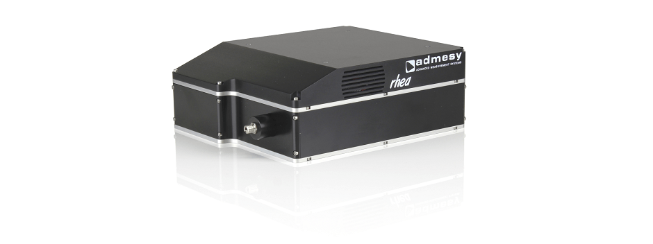
The Rhea series of spectrometers from Admesy. Image Credit: Admesy
The Rhea has the adaptability that a spectroradiometer has for OEM integration, display, lighting and appearance measurements in both production and laboratory environments. The system is extremely sensitive, it has excellent linearity and it possesses a cooled high-end CCD detector (-10 °C). The Rhea measures distinct parameters such as CCT, CRI, Yxy, radiometric and photometric, spectrum, PAR. Functions include: auto range, dark current compensation, integrated filter wheel with ND filters and shutter function and a high optical throughput design. More fundamental in radiometry, the system gives internal calculations for the standard parameters.
The Hera is an accurate spectroradiometer with auto range function and excellent linearity in a robust and compact housing. Spectral ranges include VIS and UV-NIR: 380-780 nm, 360-830 nm, 200-1100 nm.
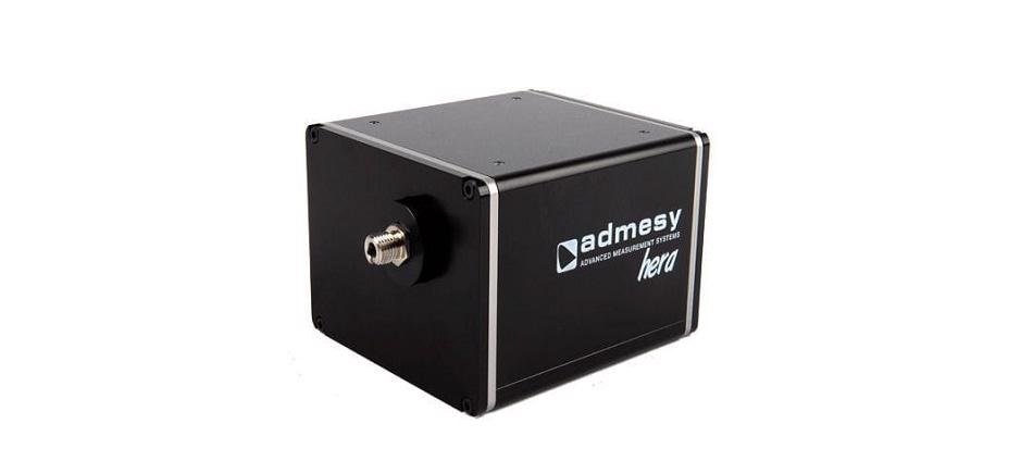
The Hera series of spectrometers from Admesy. Image Credit: Admesy
The Hera is available with a fixed [lens or cosine corrector] or fiber optics setup. It is designed to measure various parameters including xy, CRI, CCT, radiometric and photometric, PAR, spectrum. There is an auto-range function and this is combined with excellent linearity and dark current compensation. The Hera’s flexibility makes it ideal for a range of lighting development applications.
Overcoming New Obstacles in LED Development
At present, the LED industry is facing a problem. Heating effects are making it hard to calculate new style LED performance correctly. Measurements that were easy to perform before are now more tricky because the LED junction and phosphors heat up in the course of the measurement.
Even if heating is at a minimum, heated phosphors and junctions create less light, and the emitted light is moved in peak wavelength. This causes the R&D to become more complicated and makes it hard to exchange measurement data that represents the correct use of the light source. Therefore, it is difficult to precisely rate LEDs at their true output.
Additionally, an inherent challenge to the production process of LEDs and Solid-State Lighting products is driver-related variations in visual characteristics such as brightness, color and flicker, this can even occur across the same production batch. To ensure quality and consistency, it is crucial to measure these optical characteristics when developing the LED and accomplish a 100% inspection throughout the production processes.
The Hera and the Rhea are ideal spectrometers for LED development. Both spectrometers posses a robust housing, optimized for harsh production environments. This is perfect for assessing new style LED’s where significant cooling could be required to test their functional parameters. Both devices also have the flexibility to test a scope of parameters and process the data for use in a high-throughput production environment.
Combined with the Asteria light meter, Admesy allows the performance of a full inspection in production lines with high accuracy, repeatability and speed.
 Download the Brochures for More Information
References
- Arecchi, A.V., Messadi, T., and Koshel, R.J. (2007). Field Guide to Illumination. SPIE Press, Bellingham, Wash.
- Rolf R. Hainich, Oliver Bimber, Displays: Fundamentals & Applications, Second Edition
- McCluney, W.R. (1994). Introduction to Radiometry and Photometry, Artech House, Boston and London.
- Smith, W.J. (2007). Modern Optical Engineering, 4th Ed., SPIE Press, McGraw-Hill, New York.
- Wolfe, W.L. (1998). Introduction to Radiometry, SPIE Press, Bellingham, Wash
- Jeff Hulett, Ensure your light measurement method doesn't undervalue your LEDs, LED’s Magazine, March 8, 2017
This information has been sourced, reviewed and adapted from materials provided by Admesy.
For more information on this source, please visit Admesy.