Oil refineries are massive producers and consumers of hydrogen gas. Hydrogen plays a key part in numerous refining operations, from hydrocracking, which is the reduction of heavy gas and gas oils to lower molecular weight components, to catalytic reforming and treatment of gas streams.
In catalytic reforming, the gas is also utilized to stop carbon from reacting with the catalyst to maintain the production of lighter hydrocarbons and to extend catalyst life. Not surprisingly, refineries utilize huge amounts of hydrogen which may be purchased from hydrogen production facilities or produced on-site.
The demand for hydrogen is rising. Alterations to diesel fuel and gasoline specifications prompted by environmental legislation have led to more hydrogen utilization for enhancing the grade of gasoline. New investments are being made in more extensive hydrotreating and hydrocracking applications and conversion processes.
The growth and scale of hydrogen demand bring about fundamental questions concerning safe hydrogen employment. Within the processing plant environment, hydrogen’s chemical properties pose unique challenges.
Hydrogen gas is not detectable by human senses and is odorless and colorless. It is lighter than air and so it is challenging to detect where accumulations cannot occur. Hydrogen gas is also undetectable via infrared gas sensing technology.
The safety risks posed by hydrogen gas itself are added to the challenges of detection. In this article, a practical method for the deployment of fire and gas detectors that maximize detection efficiency is outlined.
This technique is based upon the notion that any single detection method is unable to respond to all hazardous events and consequently, the risk of detection failure is decreased by deploying devices that provide different limitations and strengths.
Improved Safety Through Diversity
Hazards that are associated with hydrogen include component failure, respiratory ailments, ignition, and burning. Although in most instances, a combination of hazards happens, hydrogen’s main hazard is the production of a flammable mixture which can lead to explosion or fire.
Hydrogen is easily ignited, as the minimum ignition energy of hydrogen in air at atmospheric pressure is around 0.2 mJ. Furthermore, because of hydrogen embrittlement, hydrogen can produce a mechanical failure of containment vessels, piping, and other components.
Long-term hydrogen gas exposure may result in some plastics and metals loss of strength and ductility, resulting in the formation of cracks and eventually, possible ruptures.
A form of hydrogen embrittlement occurs via chemical reaction; hydrogen reacts with one or more components of metal walls at high temperatures, to form hydrides that weaken the material’s lattice structure. In oil refineries, loss of gas containment is the first step in fire escalation and detonation.
Hydrogen leaks are usually caused by valve misalignment, defective gaskets or seals, or failures of flanges or other equipment. Hydrogen diffuses quickly when released, if the leak happens outdoors, cloud dispersion is influenced by wind direction and speed and can be affected by nearby structures and atmospheric turbulence.
With gas dispersed in a plume, detonation may happen if the hydrogen and air mixture is within the explosion range and an appropriate ignition source is available. A flammable mixture such as this can form at a considerable distance from the leak source.
Fire and gas detection system manufacturers work within the construct of layers of protection to decrease hazard propagation in order to address hazards posed by hydrogen.
Using a model such as this, each layer acts as a safeguard, stopping the hazard from becoming more severe. A hydrogen gas leak hazard propagation sequence is illustrated in Figure 1.
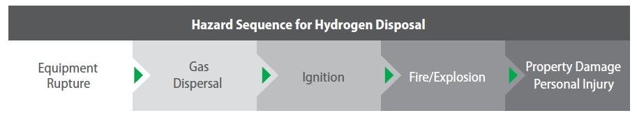
Figure 1. Hazard sequence for hydrogen dispersal. Layers of protection separate each hazard state.
Detection layers encompass different detection methods which either enhance scenario coverage or increase the likelihood that a specific type of hazard is detected.
These fire and gas detection layers can be made up of catalytic sensors, fire detectors, and ultrasonic gas leak monitors (Figure 2). Ultrasonic gas leak detectors can respond to high-pressure releases of hydrogen, like those that may happen in hydrogen separators or hydrocracking reactors.
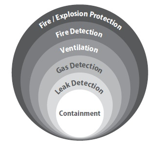
Figure 2. Schematic of protective barriers for a hydrogen accident sequence.
In turn, continuous hydrogen monitors like catalytic detectors can add to the detection of small leaks, for instance, due to a flange that is slowly deformed through utilization or failure of a vessel maintained at close to atmospheric pressure.
Hydrogen-specific flame detectors can supervise entire process areas in order to further protect a plant against fires. Such wide coverage is needed; a fire may ignite at a considerable distance from the leak source because of the hydrogen cloud movement.
When a containment system fails, hydrogen gas escapes at a rate that is proportional to internal system pressure and orifice size. These leaks can be detected using ultrasonic monitors that detect airborne ultrasound produced by turbulent flow above a predefined sound pressure level.
Using ultrasound as a proxy for gas concentration is a huge benefit of this method, as ultrasonic gas leak detectors do not require the transport of gas to the sensor element to detect gas (unlike traditional point detectors), and are unaffected by leak orientation, gas plume concentration gradient and wind direction.
Features such as these permit ultrasonic gas leak detectors to be a perfect choice for the supervision of pressurized pipes and vessels in well ventilated, open areas. Ultrasonic gas leak detectors supervise areas for noise above 24 kHz.
Frequencies that are in the audible range, spanning approximately 20 Hz to 20 kHz, are removed by a bandpass filter. Another benefit of these instruments is their large coverage area per device.
For example, depending upon the level of background ultrasound, a single detector can respond to a small hydrogen leak at around 8 m from the source. Even small leaks can produce sufficient ultrasonic noise for detection within most industrial environments, as shown in Figure 3.
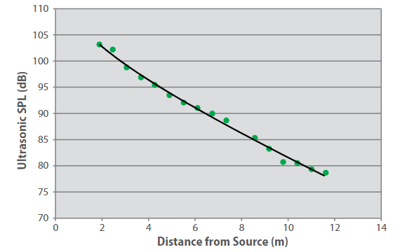
Figure 3. Sound pressure level as a function of distance for hydrogen leaks.
Leak size = 1 mm-diameter orifice, differential pressure = 5,515 kPa (800 psi), leak rate = 0.003 kg/s. The curve is to guide the eye.
While in industrial sites audible acoustic noise usually ranges between 60 and 110 dB, ultrasonic noise levels (frequency range of 25-100 kHz) span from 68 to 78 dB in high noise areas where rotating machinery like turbines and compressors are installed, and rarely exceed 60 dB within low noise areas.
So, ultrasonic gas leak detectors are able to detect hydrogen leaks without being affected by background noise. Ultrasonic gas detectors can also alarm rapidly, often within milliseconds, as these instruments respond to the gas release instead of the gas itself.
Direct gas detection using catalytic bead sensors is a second protective measure that has been utilized for hydrogen applications for over 50 years. These sensing devices are made up of a pair of platinum wire coils embedded in a ceramic bead.
The active bead is coated with a catalyst; the reference bead is encased in glass and consequently is inert. Upon exposure to hydrogen, the gas starts to burn at the heated catalyst surface per the reaction:
2H2 + 2O2 → 2H2O + O2.
Hydrogen oxidation releases heat, which causes the wire’s electrical resistance to alter. This resistance is proportional to concentration and linear over a large temperature range (~ 500 – 1000 °C).
The reaction temperature and catalyst are tailored to prevent the combustion of hydrocarbons in the substrate for hydrogen-specific catalytic detection. The simplicity of this scenario permits catalytic detectors to be suitable for numerous applications.
Catalytic sensors can determine hydrogen presence with fair accuracy and repeatability where gas accumulations can happen. Hydrogen-specific catalytic detectors also provide quick response times, usually 5 to 10 seconds, and provide good selectivity.
Among sensor manufacturers, these parameters vary widely but are usually tailored for maximum selectivity and speed of response. As referenced earlier, hydrogen is unable to be detected by infrared absorption, enabling catalytic detection to be a highly reliable technology for hydrogen gas detection.
In addition to catalytic and ultrasonic gas leak detectors, hydrogen-specific flame detectors add another barrier against hydrogen hazard propagation. These instruments monitor infrared and ultraviolet radiation simultaneously at different wavelengths.
Radiation is emitted in the infrared by water molecules created by hydrogen combustion; emission from this steam or heated water is monitored in the wavelength range from 2.7 to 3.2 mm.
An algorithm that processes IR radiation modulation enables these detectors to avoid false signals caused by solar reflection and hot objects. Usually, the UV detector is a photo discharge tube which detects deep UV radiation in the 180 to 260 nm wavelength range.
Solar radiation at these wavelengths does not reach the earth’s surface because of absorption by the atmosphere; so essentially, the UV detector is immune to solar radiation. This combination of IR and UV detection heightens false alarm immunity while producing detectors that can detect even small hydrogen fires at a range of 5 m.
The detection range of a hydrogen-specific flame detector for a plume 15 – 20 cm (6 – 8 inches) high and 15 cm (6 inches) in diameter is shown in Figure 4. As seen in this instance, the flame detector is able to detect the on-axis range of 4.6 m (15 ft) up to ± 55°, providing broad angular coverage.
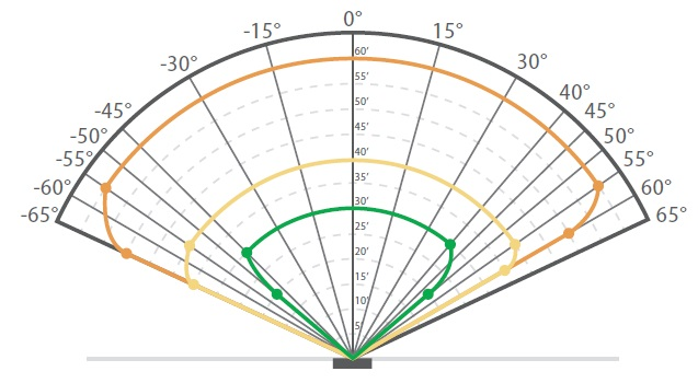
Figure 4. The detection range of an FL500 UV/IR – H2 Detector.
Size of hydrogen fire: 15 cm (6 in) diameter and 15 – 20 cm (6 – 8 in) high.
Catalytic bead gas detection, ultrasonic gas leak detection, and hydrogen flame detection have different vulnerabilities and strengths and respond to different hazard manifestations – whether the gas, the source of the gas, or the fire.
In addition, each technology operates in a different area of regard, with catalytic detectors as point instruments and ultrasonic leak detectors and hydrogen flame detectors as area monitors.
As for their unique properties, the combination of detectors heightens the odds that hydrogen fire or gas dispersal is identified early on, either when an explosion occurs or before ignition. An illustration of the utilization of these technologies can be seen in catalytic reforming1.
Using this process, a stream of heavy gas oils is exposed to high temperature (480 – 524 °C) and pressure (1,379 – 3,447 kPa; 200 – 500 psi) and passed through a fixed-bed catalyst. The oils are converted to aromatics that yield much higher octane ratings for gasoline upon reaction.
Due to the continuous hydrogen production and operating conditions, a rupture in the reactors, pipe system, or separator of the unit can have grave consequences. The detector allocation across a reforming unit is shown in Figure 5.
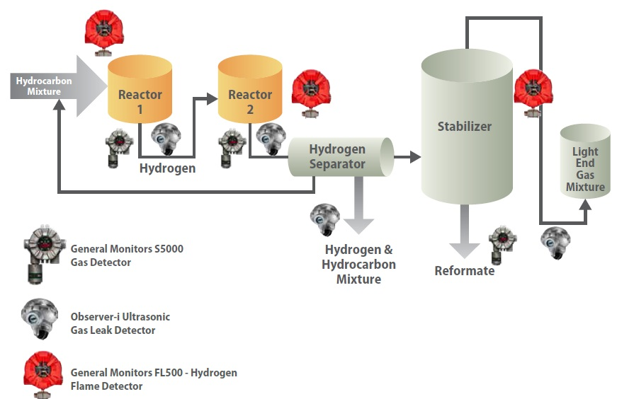
Figure 5. Schematic of the dual-stage reforming unit showing possible locations of gas and flame detectors.
Of course, the scheme which is illustrated in this example does not preclude the utilization of other detection systems, nor does it eliminate the requirement for operating procedures, instrumentation and control systems, and adequate training, which are all necessary for safety.
Condition monitoring instruments like x-ray pipe testing equipment play a key role in identifying defects before the loss of pipe network integrity. As such, thermal conductivity sensors can ensure detection coverage within oxygen-deficient environments and so complement catalytic sensors, when employed above the LEL.
Experience suggests that the selection of detection instruments must be weighed carefully in order to match the hazard types associated with the particular refinery’s chemical process and that each detection type offsets vulnerabilities of the other.
Conclusion
Fueled by environmental legislation and demand for cleaner, higher-grade fuels, hydrogen production continues to grow. Yet, rising production must be matched by a comprehensive approach to plant safety.
New facilities that utilize hydrogen must be designed with adequate safeguards from potential hazards; to ensure that sufficient barriers are available to minimize accidents and control failure, the design of old facilities should also be revisited.
Safety systems that deploy a range of detection technologies can counteract possible effects of leaks, fire, and explosions, stopping property or equipment damage, personal injury, and loss of life.
As they are complementary, a combination of catalytic and ultrasonic gas leak monitors and flame detectors is especially effective. Vulnerabilities of one are offset by the strengths of the others; hazards have less opportunity to propagate undetected.
Combined with a design that prevents leakage and eliminates possible ignition sources, such diverse safety systems provide a sound approach for managing hydrogen processes.
References
- Berger, W. D. and Anderson, K. E., Modern Petroleum: A Basic Primer of the Industry, Second Edition, PennWell Publishing, Tulsa, Oklahoma, 1981.

This information has been sourced, reviewed and adapted from materials provided by MSA - The Safety Company.
For more information on this source, please visit MSA - The Safety Company.