In this interview, AZoM talks to Daniel Brau, Managing Director of Photonic Science, about the working principles of diffraction Laue cameras, and what makes Photonic Science's Laue crystal orientation systems so special.
How does Photonic Science’s Laue camera system work?
The Laue technique uses a back reflection geometry. We use a polychromatic low energy X-ray beam that runs through a detector and a sample that is situated on the other side of the detector. This reflects the X-ray beam and creates a set of diffraction spots that are then recorded directly onto the detector. Indexing the diffraction pattern is specific for each crystal orientation, which enables materials scientists and physicists to grow and then cutting crystals with electro-optical properties.
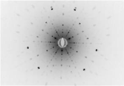
Laue Spots Sapphire Sample C-axis aligned.
What is Laue diffraction?
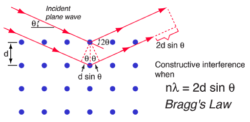
Going into detail on the physics of Laue cameras, they work by using X-rays that interact with electron clouds on a single crystal or an alloy. Bragg’s Law comes into play with Laue diffraction. Bragg’s Law is when the incident angle of the X-ray beam makes it so the difference in X-ray path lengths between the crystal planes is an integer number of wavelengths meaning that constructive interference occurs, which creates a diffracted beam.
If the reflected beam satisfies this law, the reflected beam is recorded onto the Laue detector. Overall, it is a relatively simple equation, which allows you to locate the spots according to a specific orientation of a crystal.
How do you acquire a Laue diffraction pattern?
For instance, if I wanted to measure a mis-cut angle from a crystallographic orientation down to < 0.1-degree accuracy, I would overlay a theoretical pattern onto an experimental one and then record the deviation from the theoretical spot position. The Bragg equation would let me derive the exact misorientation over a three angular axis of the crystal lattice with Photonic Science’s Laue software that was built to be dedicated to this purpose.
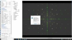
PSEL dedicated Laue software.
What components make up a Laue system?
Photonic Science’s Laue systems offer a high-brightness, micro-focus X-ray source, along with a low-noise, large-area X-ray detector. Along with this is either a manual or motorized stage where the sample is positioned. Historically, two kilowatt X-ray sources have been used in Laue cameras, but doing this required complicated cooling setups and the installations used a lot of power. Nowadays, only 25 W of effective power is needed for a Laue system.
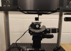
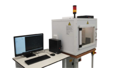
Vertical Laue system.
What are the benefits of the Photonic Science Laue system?
Our system can cope with sub-millimeter range samples because it operates with a much smaller X-ray beam footprint that is delivered onto the sample. This, in conjunction with a large area, high-resolution detector, it is possible to reach orientation accuracy down to 0.05 degrees. Additionally, the system geometry can handle wafers and large ingots, along with larger components like turbine alloys.
What other features set Photonic Science’s Laue cameras apart from other systems available on the market?
As I have mentioned before, the X-ray beam footprint is a lot smaller. This means that our system can help material scientists and physicists identify subgrain structures and orientation. The system is able to acquire up to 10,000 orientation measurements automatically on large polycrystalline samples like solar cells, for example, which aids in understanding the effect of grain orientation versus cell efficiency.
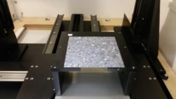
Polycrystalline Silicon Wafer Scanner.
The system also comes with a range of accessories; could you talk us through what is available?
The Photonic Science systems can be customized to suit a user’s environment and particular requirements. Usually, we provide a turn-key solution to users, as well as sample holders, goniometers, and scanning stages used to align crystals on a routine basis before they are transferred to an appropriate cutting tool.
Automatic batch testing is applied to detector materials such as CdTe, GaAs, microelectronic substrates such as GaN, and piezo materials cut and diced as wafers. We will have sample holders capable of hosting up to 100 samples, and these can all be scanned using a single press button procedure.
Laser materials and sapphire are available in large bulk, heavy-duty stages. These are used to accommodate samples that can be anywhere from 10 kg up to >100 kg.
Thin-film orientation such as AlN is also controlled with the finest precision stages featuring a multi-point scanning routine.
Laue Crystal Orientation System.
What other information would you like readers to know?
To begin with, Photonic Science started selling these systems and cameras just for scientific applications. Now, we are producing Laue diffraction systems more often for industrial applications. Our systems are built to purpose, unlike old-fashioned and expensive diffraction systems. Currently, we have over 200 systems in operation in the field.
About Daniel Brau
 Daniel studied Physics at Imperial College London and Universite of Paris Sud where he specialized in material science and thin film deposition. He joined Photonic Science in 1995 heading up the French Office in Grenoble. He was in the Sales and Marketing of Scientific Manager for Industrial and Surveillance cameras and Systems. In 2018 he moved to the UK company where he is now Managing Director. Daniel has been instrumental in the development of the company strategy and is heavily involved in new product innovation. He introduced one of the very first Laue systems to the market with the Institute Laue Langevin in 2011 and SWIR / InGaSa cameras in 2013. Daniel has a keen interest in X-ray detectors and has a very wide knowledge of both the technology and applications suited to these products.
Disclaimer: The views expressed here are those of the interviewee and do not necessarily represent the views of AZoM.com Limited (T/A) AZoNetwork, the owner and operator of this website. This disclaimer forms part of the Terms and Conditions of use of this website.