Using the Kerr effect, achieve efficient development and quality control of better performing magnetic steel alloys for electrical and electronic applications.
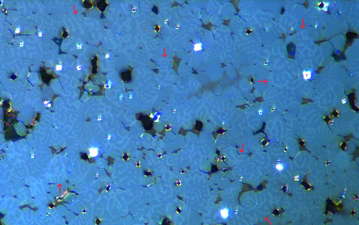
Image Credit: Leica Microsystems GmbH
The Kerr effect causes polarized light to rotate after interacting with magnetic domains in a material and enables the investigation of magnetized samples using Kerr microscopy. This method allows the visualization of magnetic domains on the material's surface.
Kerr microscopy can also play an important role for efficient R&D and quality control of magnetic materials, such as steel alloys, used in electrical and electronic equipment.
This article describes Kerr microscopy, revealing how it can be used to image magnetic domains in steel alloy grain structures.
Magneto-Optical Kerr Effect
In the 1870s, scientist John Kerr discovered a magneto-optical phenomenon that was later named after him: the magnetic optical Kerr effect. He discovered that the polarization plane of linearly polarized light rotated following reflection from the surface of an iron magnet.1-3 The intensity of the effect is determined by the magnetic domain dipole component that runs parallel to the reflected light beam.
Oblique incident light is required for magnetic domains parallel to the surface plane. Known as the longitudinal Kerr effect (see Figure 1A), it produces a maximum Kerr signal intensity when an incident light plane is parallel to the domain's magnetization. However, when the magnetic domains are perpendicular to the surface's plane, then normal incident light produces the highest signal intensity. Figure 1B demonstrates this case, known as the polar Kerr effect.
However, this article will solely consider the longitudinal Kerr effect.
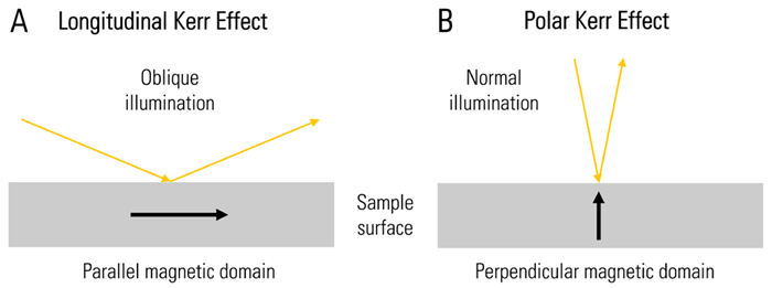
Figure 1. Schematic showing the A) longitudinal and B) polar Kerr effect. Image Credit: Leica Microsystems GmbH
Many electrical and electronic devices and products use magnetic materials: electromagnets, transformers, windings/coils, inductors, filters, and storage media. Inductors are used to limit current in electrical lines, store energy in the form of an intermediate magnetic field, match impedance, and filter.
Filters in electrical circuits adjust the amplitude and phase of an electrical signal based on its frequency. Hard disks or hard drives store data on the spinning disk surface using magnetic material. These electrical devices will often require the use of a magnetic substance made of iron, such as a steel alloy.
Steel alloy magnetization causes magnetic domains with dipoles to form within the metal grains. Due to the Kerr effect, magnetic domains within steel grains can be optically imaged. They can be seen within the grains on the surface of a steel sample using Kerr microscopy.4-6
Further, Kerr microscopy can help with the research and development (R&D) of better performing steel alloys for electrical and other applications, as well as inspection, quality control (QC), and failure analysis.4
Challenges When Imaging Magnetic Steel with Kerr Microscopy
Observing magnetic domains in steel alloy samples using Kerr microscopy poses certain challenges.
Temperature-treated (heated or cooled) steel grains with magnetic domains frequently lack a cubic crystal structure.6,7 As a result, while cutting a sample from such a steel alloy, careful consideration of position and orientation is required. If the cutting direction is incorrect, the Kerr effect will not be seen.
The steel samples must be flat and smooth on a size scale that equals or exceeds the desired lateral resolution.3
The highest resolution for conventional optical microscopy is around 0.25 μm, so magnetic domains must be greater than this to be observed. Only magnetic domains at the surface, i.e., within 10 nm of the visible light penetration depth, can be seen.3
As such, Kerr microscopy can only be used to investigate magnetic domains on the sample surface, which may differ from bulk volume domains.
Because the Kerr effect may not be so strong, depending on the magnetic domains of the steel alloys studied, particularly in the longitudinal case, polarized incident light with sufficient intensity to observe and record the effect is required.
What is Necessary for Kerr Microscopy?
The setup of a conventional optical compound microscope can be improved for visualizing the Kerr effect. However, correct preparation of steel alloy samples is crucial.
Steel Sample Preparation
The samples were cut from a carbon steel alloy that has been heat- or cold-treated. This alloy is used in electrical applications. The samples were ground and polished with diamond paste to achieve a smooth surface suitable for imaging with Kerr microscopy.
Setup of a Microscope for Kerr Effect Imaging
To study the longitudinal Kerr effect in opaque magnetic steel samples, set up the optical microscope (for this study the DM6 M, see figure 2) as follows:
- Light must pass through two polarizers, one before and one after the sample surface, at an angle of less than 90 degrees.
- To improve the weak Kerr effect, a Smith reflector is used to polarize incident light.
- An external light source (EL6000) can be utilized to boost light intensity.
- Imaging of steel alloys can require an objective with a magnification of 10x, 20x, 50x, or 100x, depending on the grain size.
- To achieve oblique illumination, use a small aperture diaphragm positioned off-center.
- To capture images of the Kerr effect, which is sensitive to light, a microscope camera with high gain, such as the K5C, is necessary.
- When recording color or black and white images with the camera, boost the contrast or gamma setting.
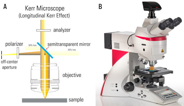
Figure 2. Optical path (A) in the DM6 M (B) materials microscope which was used here for longitudinal Kerr microscopy imaging of magnetized steel. Image Credit: Leica Microsystems GmbH
Results from Imaging Magnetic Steel with Kerr Microscopy
The results of Kerr microscopy imaging of steel samples can be seen in Figures 3 and 4 below.
The longitudinal Kerr effect causes the magnetic domains in the grains of the steel samples to produce bright and dark patterns in the images.
The rotation of polarized light after interaction with magnetic domains might result in stronger (brighter) or weaker (darker) Kerr signals, or even extinction, after passing through the analyzer.
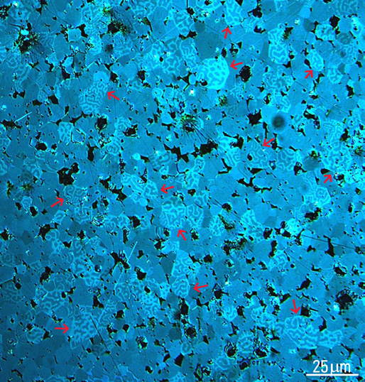
Figure 3. Kerr-microscopy image of a magnetized steel sample where the grains show light and dark patterns (marked with red arrows) due to the longitudinal Kerr effect. Image Credit: Courtesy of Florian Lang-Melzian, Robert Bosch GmbH, Germany
More Kerr-microscopy images of the same magnetized steel sample were captured, progressing from an overview to a more detailed view, using objectives with magnifications of 20x, 50x, and 100x. Figure 4 below shows some examples.
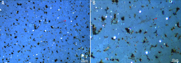
Figure 4. More images of the magnetized steel sample mentioned in Figure 2 were recorded with an objective having a magnification of A) 50x and B) 100x. The light and dark patterns in the grains due to the Kerr effect are visible. An example is indicated with a red arrow in both images. Image Credit: Courtesy of Florian Lang-Melzian, Robert Bosch GmbH, Germany
The preceding results demonstrate that Kerr microscopy can swiftly visualize magnetic domains in the grains of steel alloys.
Summary and Conclusions
Kerr microscopy, which uses the longitudinal Kerr effect, is an effective approach to visualize magnetic domains in materials such as steel alloys. Its use in R&D, quality control, and failure analysis can aid in the development of better-performing electrical and electronic equipment, such as inductors, filters, and hard drives.
Kerr microscopy allows for rapid imaging of magnetic domains on the surface of materials, which benefits the electrical and electronics industries.
References
- Weinberger, P. (2008). John Kerr and his effects found in 1877 and 1878. Philosophical Magazine Letters, 88(12), pp.897–907. DOI: 10.1080/09500830802526604. https://www.tandfonline.com/doi/abs/10.1080/09500830802526604.
- Oppeneer, P.M. (1999). Theory of the Magneto-Optical Kerr Effect in Ferromagnetic Compounds. (online) DOI: 10.13140/2.1.3171.4083. https://www.researchgate.net/publication/272065058_Theory_of_the_Magneto-Optical_Kerr_Effect_in_Ferromagnetic_Compounds.
- J. McCord, Magneto-optical microscopy, Abstract, European School on Magnetism: New Experimental Approaches in Magnetism, September 7-16, 2005, Constanta, Romania. Available at: https://magnetism.eu/esm/2005-constanta/abs/mccord-abs.pdf
- Moses, A.J., Williams, P.I. and Hoshtanar, O.A. (2005). A novel instrument for real-time dynamic domain observation in bulk and micromagnetic materials. IEEE Transactions on Magnetics, 41(10), pp.3736–3738. DOI: 10.1109/tmag.2005.854924. https://ieeexplore.ieee.org/document/1519428.
- McCord, J. (2015). Progress in magnetic domain observation by advanced magneto-optical microscopy. Journal of Physics D Applied Physics, 48(33), pp.333001–333001. DOI: 10.1088/0022-3727/48/33/333001. https://iopscience.iop.org/article/10.1088/0022-3727/48/33/333001.
- Jovicevic-Klug, M., et al. (2021). Investigation of microstructural attributes of steel surfaces through magneto-optical Kerr effect. Journal of Materials Research and Technology, 11, pp.1245–1259. DOI: 10.1016/j.jmrt.2021.01.106. https://www.sciencedirect.com/science/article/pii/S223878542100106X.
- H. Föll, Be Cool!, Section 8.4, Carbon Steel, Chapter 8 in Iron, Steel and Swords (MAT, Universität Kiel, Germany).

This information has been sourced, reviewed, and adapted from materials provided by Leica Microsystems GmbH.
For more information on this source, please visit Leica Microsystems GmbH.