In the mid-twentieth century, sensor technology in cars was limited to mechanical or electromechanical instruments, such as tachometers or rev counters. By the early 2000s, however, cars contained a large number of microprocessor-controlled electronic sensors and actuators that performed sophisticated measuring, monitoring, and control activities.
At the time, non-contact optical metrology technologies were essential for the development and production of these silent assistants.
These automotive sensor elements were largely implemented as micro-components known as MEMS (Micro-Electro-Mechanical Systems). MEMS compactly integrate mechanical, electrical, and electronic functionalities on one chip, enabling them to interact with their surroundings as sensors or actuators.
Therefore, a MEMS-based system can respond electrically or mechanically to physical or chemical ‘stimulants’. As MEMS components in cars took on more safety-related functions in the early 21st century, achieving high sensor precision and long-term reliability was critical.
To meet these quality standards, precise measurement technology was required to characterize and validate the system attributes of prototypes during development and to control measurements during MEMS manufacturing.
Automotive MEMS Required Reliability
In the early 2000s, MEMS applications included brake systems, airbag control, and dynamic stability control systems.
Individual components were exposed to harsh environmental conditions throughout their lifespan, such as vibration, temperature variations, and corrosion, thereby requiring high reliability. As a result, the defect rates associated with the service life of these components were only a few parts per million.
The precision required for sensors in the automotive industry was on the order of 1 % over the component's lifetime, corresponding to 15-20 years or around 200,000 kilometers of operational performance. Of course, these standards had to be accomplished with the lowest feasible production costs.
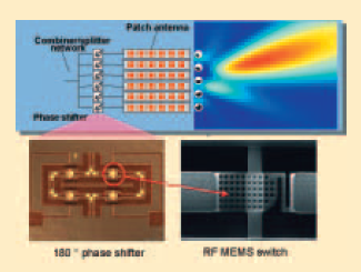
Figure 1. Design of a patch antenna. Image Credit: Polytec
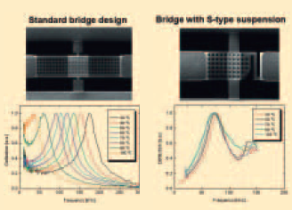
Figure 2. Resonance measurement on MEMS switches. Image Credit: Polytec
Vibrometry Makes it All Possible
Laser Doppler Vibrometry is a flexible, high-precision measurement tool that plays an important role in rapidly, without reaction, and precisely assessing the mechanical properties of MEMS, ensuring component quality. Single-point vibrometers can be used to measure system resonances in components.
Specialized microscope-scanning vibrometers make it possible to measure MEMS motion across the entire surface of a component quickly and over a wide frequency range. Animated visualizations of the operating vibration shapes derived from these measurements are essential for understanding the processes under study.
Adaptive Antennas
Adaptive antennas are used in a variety of high-frequency applications. The radiation properties, or the transmit/receive direction, can be modified based on the current traffic conditions.
In radar applications, objects at varying distances can be recognized by sequentially scanning the radiation angle and measuring the time it takes for the radiation to reach the object and return. The radiation properties can be adjusted using planar patch antennas that have no moving parts.
Their radiation lobe is caused by the interference of electromagnetic waves emitted by several single-antenna elements (‘patches’). The patches are interleaved in rows and columns, resulting in a fixed phase relationship. This necessitates the use of special phase shifters, which can be implemented using microsystem technology.
The phase shifters include a variety of RF MEMS switches that set a fixed phase relationship (Figure 1). Bosch development engineers aimed to achieve a clearly defined switching performance that was independent of ambient conditions and remained constant throughout the component's life.
MEMS Design and Vibration Properties
The switch, first created by the engineers with a typical bridge design, demonstrated switching performance that depended on ambient temperature, as evidenced by the shift in bridge resonance measured with the vibrometer (on the left of Figure 2).
This was because the aluminum bridge and silicon substrate had different thermal expansion coefficients. This effect could be greatly mitigated by altering the bridge shape, as illustrated in the spectrum on the right side of Figure 2.
Scanning Tests
Testing switching performance in the time domain revealed significant bouncing or ringing. To provide a picture of the component's real surface dynamics during switching, tests were performed with a Laser Scanning Vibrometer.
The visualized results revealed that, in addition to the basic vibration, the component's spectrum contained higher harmonics of the bridge surface. Laser vibrometry also gave essential structural dynamic information to help optimize the component's functionality (Figure 4).
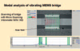
Figure 3. MEMS switch measured by the MSV-300 Microscope Scanning Vibrometer. Image Credit: Polytec
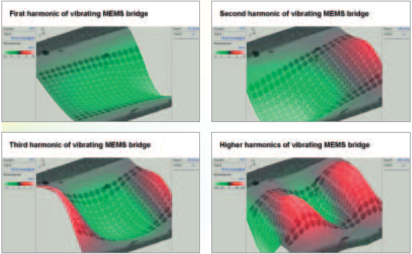
Figure 4. Deflection shapes of the MEMS switch. Image Credit: Polytec
Summary
Many of the improved safety and comfort features that were available in vehicles in the early 2000s were based on microsystems that employed cutting-edge technologies.
Optical measurement and testing processes of the time, such as Laser Doppler Vibrometry, ensured that the required functional and quality properties were met or exceeded during the development and production of MEMS elements, making travel safer than in the twentieth century.

This information has been sourced, reviewed, and adapted from materials provided by Polytec.
For more information on this source, please visit Polytec.