One possible contributor when continually encountering inconsistent creep, reduced creep life, or rupture test results is the specimen adapters used.
Alignment issues resulting from worn threads can lead to specimen bending, especially when a load is applied before the forces are sufficient to tighten the load train. Adapters that have deteriorated can cause misalignment so severe that it exceeds the testing standard requirements.
Applied Test Systems (ATS) has carried out a series of internal experiments to demonstrate this phenomenon. In this experiment, ATS focused on acquiring stress-strain data during force application. During the tests, the force was applied incrementally, and strain readings were recorded at intervals of force increases. This process is known as “hot step loading” for a creep test. Experimental conditions were performed using ATS equipment at room temperature.
The same test machine was used for each hot-load data set. Except for the specimen adapters, all load train and extensometer components were identical. Adapter thread condition was verified using go/no-go gauge standard thread checks. A total pan load of 95 lbs with a 9 lb preload on a 20:1 lever arm ratio was applied.
The main sample was a 0.25-inch-diameter specimen with a 1-inch gage length. The first data set (Test 1A) was acquired during a test using a set of worn specimen adapters (aka grips, threaded adapters, specimen couplings, etc.). There is a clear shift on the stress-strain graph at the start of the test, as well as a significant divergence of the left and right plots on the hot load graph.
Another indicator of binding issues related to alignment or the extensometer rod is the endpoint differential between the left and right extensometer data points in the hot load data. Throughout Test 1A, at the end of the hot load, the loading data endpoint showed a delta of 0.001102 inches between the left and right extensometer readings.
In both 1A and 1B, the testing procedure was performed a dozen times using a process of elimination and component corrections to determine the source of the loading issue.
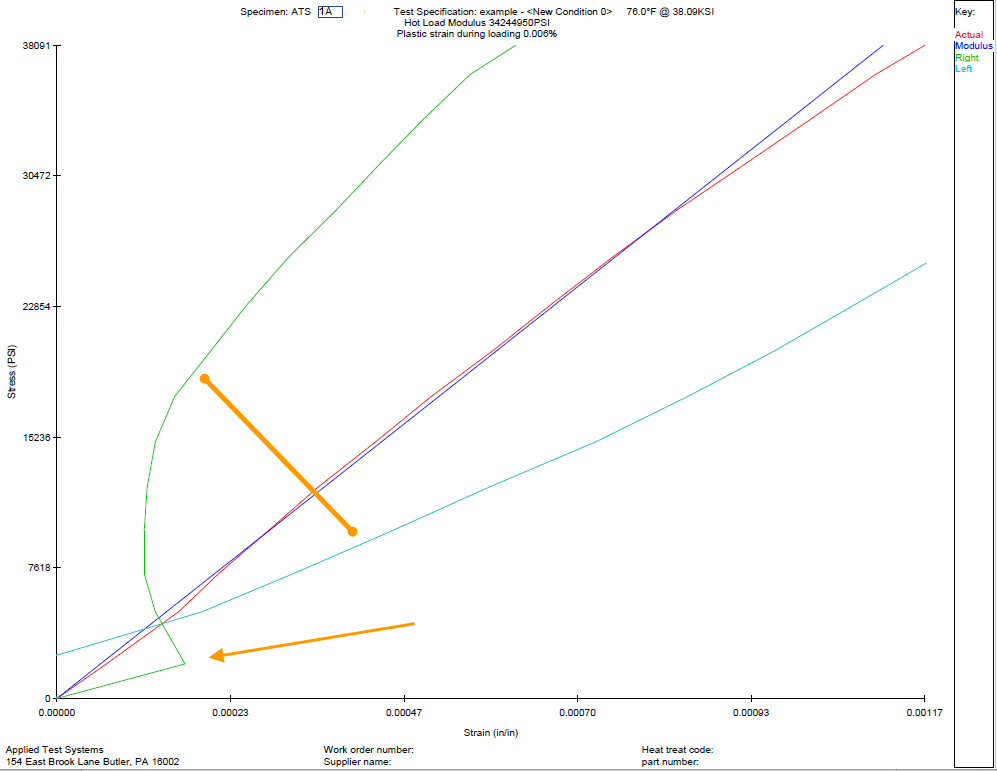
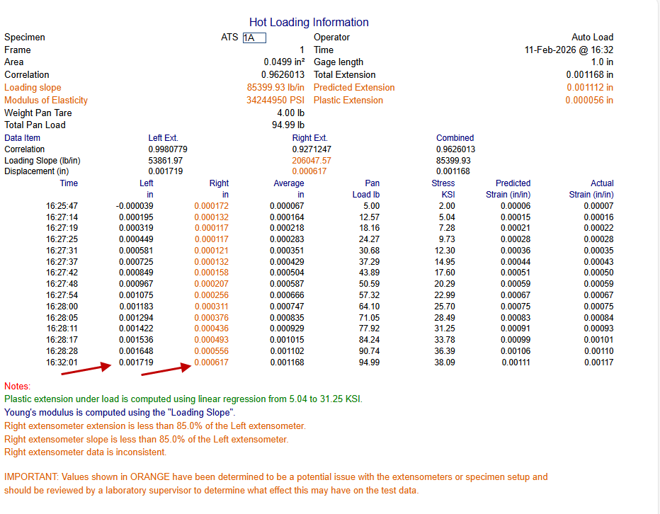
Test 1A Hot Load Graph & Report. Image Credit: Applied Test Systems
The second data set (Test 1B) shows another example of a hot load report after extracting and correcting the load train using the same specimen adapters as those used in the hot load Test 1A:
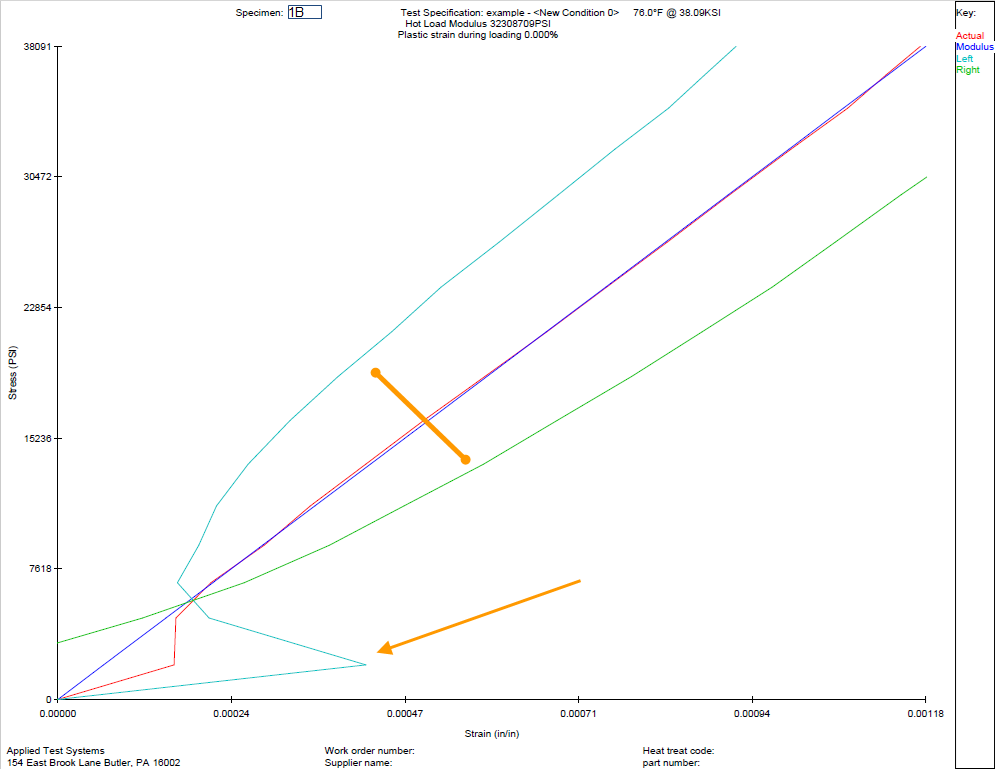
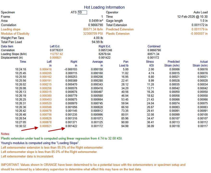
Test 1B Hot Load Graph & Report. Image Credit: Applied Test Systems
Test 1B showed a small improvement (0.000501 inches) in the endpoint difference, as shown in the hot-load report, but the initial scatter still suggests a loading issue. At this point, go/no-go checks were carried out; it was possible to thread the no-go portion into the threaded adapter's specimen thread size.
In the third data set (Test 2A), the threaded specimen adapters were replaced with a new set from ATS’s stock inventory. After conducting go/no-go checks, the load train was reassembled, and further tests were conducted. This revealed an improvement across the readings, with loading showing reduced scatter and a more constricted delta across the left and right strain plots compared to those in 1A and 1 B.
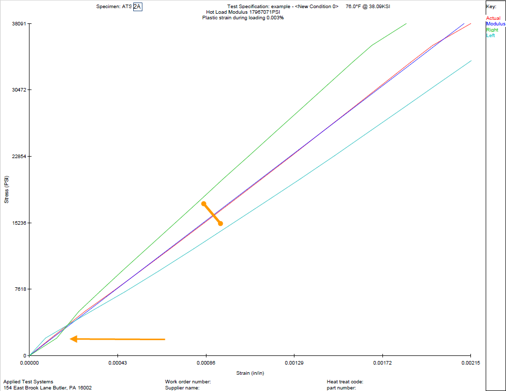
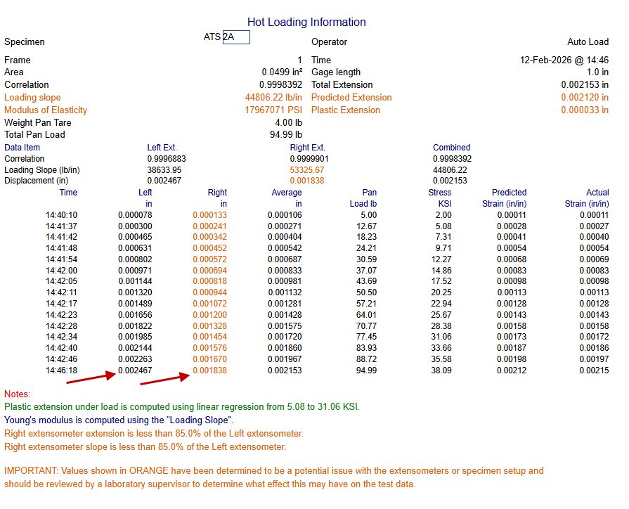
Test 2A Hot Load Graph & Report. Image Credit: Applied Test Systems
Test 2A showed that the end-point differential on the hot-load report was acceptable (0.000629 inches). Test 2B presents another example of a hot-load report after extracting and correcting the load train using the same specimen adapters as in the hot load conducted in Test 2A.
Again, improved readings were observed during loading, with reduced scatter and a further constriction of the delta in the left- and right-strain plots compared with 1A and 1B data.
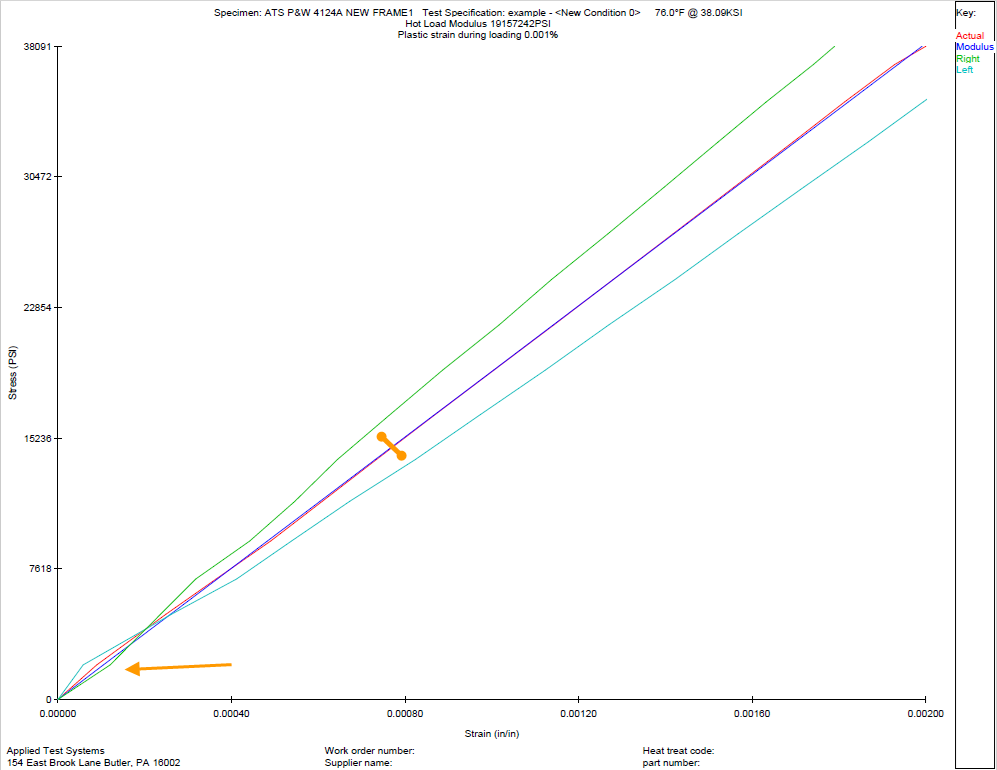
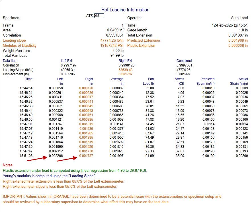
Test 2B Hot Load Graph & Report. Image Credit: Applied Test Systems
Test 2B also showed an acceptable endpoint difference on the hot-load report (0.000419 inches). While a hot load alarm would be flagged in both Tests 2A and 2B (HLE in WinCCS V8 and later software), after review, this loading data would be passed as acceptable in the majority of cases.
The load data improvements can be directly related to the condition of the threaded specimen adapter used throughout these tests. These quality checks of load train components are essential, especially when experiencing consistent creep issues or during stress rupture testing.
ATS recommends routine checks that fit with current testing schedules, and always after any extended test runs or exposure to heavy loading g and/or increased temperatures.

This information has been sourced, reviewed, and adapted from materials provided by Applied Test Systems.
For more information on this source, please visit Applied Test Systems.