Sponsored by MicrotracReviewed by Emily MageeApr 24 2026
Performance in technical ceramics is not specified at the end of processing; rather, it is engineered gradually, beginning at the particle level. The behavior of ceramic materials, whether in dry powders, concentrated slurries, or sophisticated suspensions, is essentially determined by particle size, shape, and interactions.
These parameters influence packing efficiency, flow behavior, dispersion quality, and stability, eventually determining the microstructure and functional qualities of the finished component.
Modern characterization techniques allow for the understanding and manipulation of these features with unparalleled precision.
Manufacturers can use dynamic image analysis, laser diffraction, dynamic light scattering, Zeta potential, and stability analysis to develop formulations more predictably and effectively than trial-and-error experiments.
This integrated method allows for quicker development cycles, better reproducibility, and more reliable ceramic products.
1. Engineering Performance at the Powder Stage
Ceramic extrudates play an important role in heterogeneous catalysis, especially in petrochemical processing, refinery operations, and environmental applications. These materials are typically generated as rod-shaped particles, often known as pellets, and are filled into reactors.
The extrudates' geometric qualities are critical: their length, diameter, aspect ratio, and general uniformity have a direct impact on packing density, pressure drop, mechanical stability, and gas and liquid flow behavior through the catalyst bed.
Even minor differences in particle size or shape uniformity might result in channeling, irregular residence durations, or premature mechanical degradation, whch can reduce reactor performance and catalytic efficiency. Extrusion is used to make many different ceramic components, and they are held to identical quality standards.
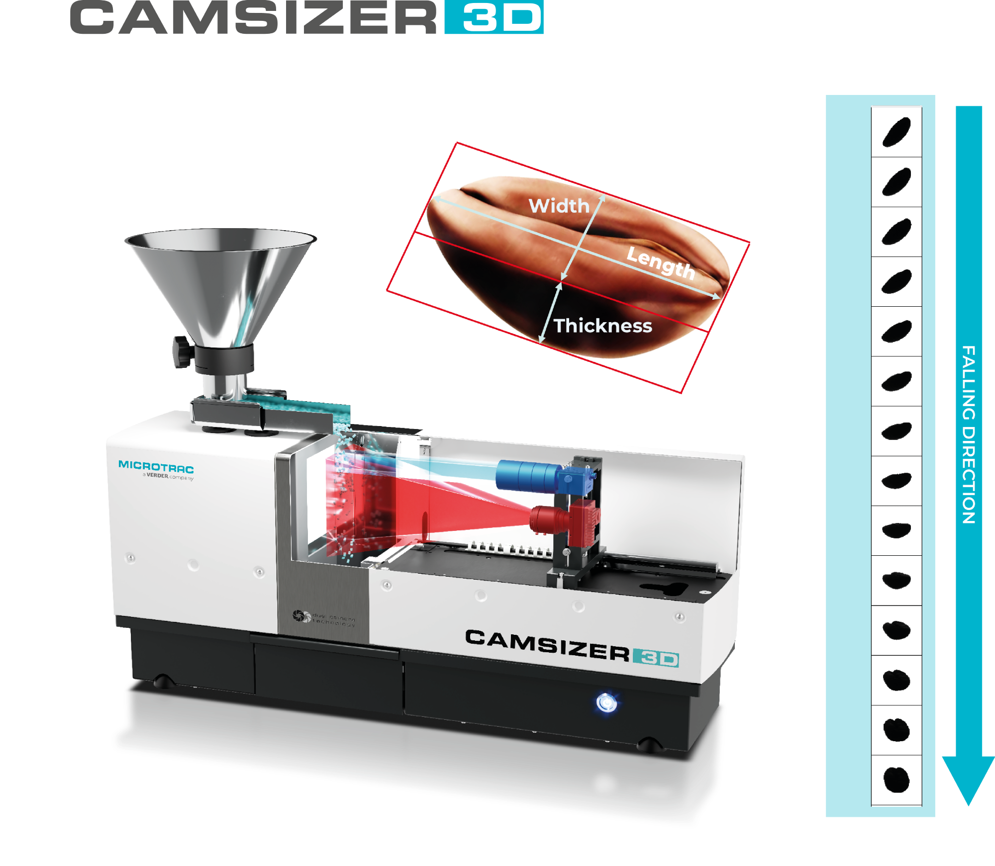
The CAMSIZER 3D Particle Size & Shape Analyzer from MICROTRAC. Image Credit: Microtrac
CAMSIZER 3D and its proprietary dynamic image analysis (DIA) technology offer a realistic approach for characterizing these particles.
Instead of using a single random projection per particle, as in typical two-dimensional DIA, each particle is monitored as it moves across the camera's field of vision. Particles are thus recorded in multiple orientations as they freely fall, facilitating precise measurement of their true dimensions.
As a result, the system can determine the actual maximum length, width, and thickness, meaning that particle geometry is captured in a manner that closely approximates genuine physical dimensions.
This difference becomes very clear when comparing measurement methods. While traditional 2D image analysis tends to underestimate particle length due to orientation effects, 3D tracking produces excellent agreement with physical caliper measurements.
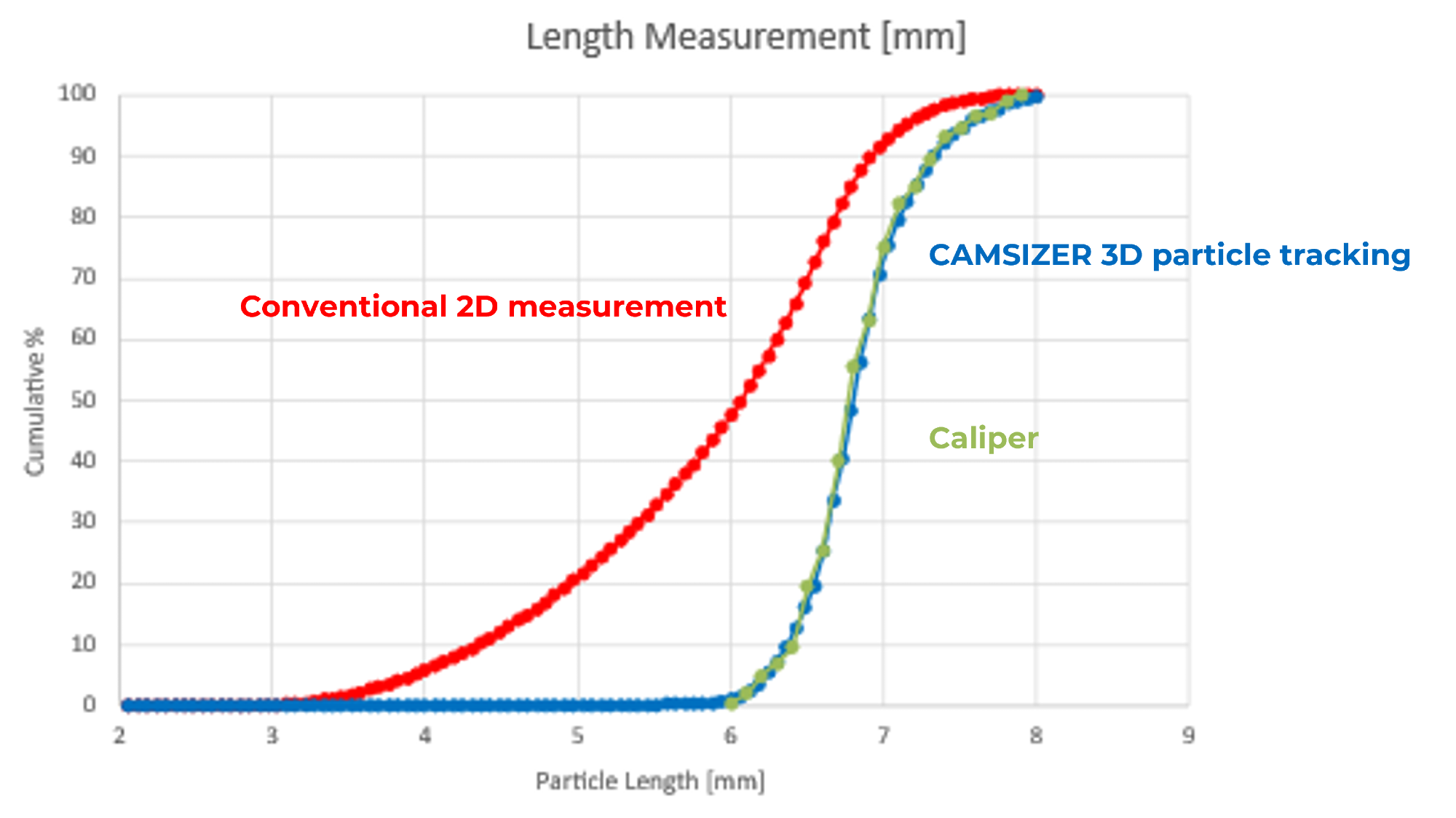
Figure 1. Particle length distribution of a ceramic extrudate sample. Image Credit: Microtrac
The impact extends beyond size into shape characterization. Two-dimensional approaches underestimate length, meaning they skew the aspect ratio, making particles appear less elongated than they actually are.
In contrast, 3D analysis generates consistent and relevant form descriptors, which are critical for understanding process behavior.
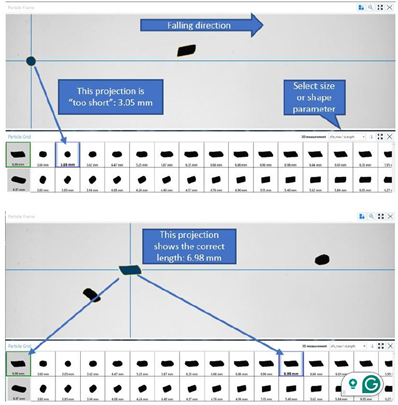
Figure 2. Analysis of particle tracks – the individual projections of one particle are listed from left to right. Image Credit: Microtrac
However, when dealing with powder systems, size distribution must be examined over a wide range. Ceramic materials frequently contain small particles in the micron or submicron range, as well as coarse particles larger than one millimeter in size.
This is evident in the example below, which compares materials like alumina, bauxite, and silicon carbide. While alumina particles have limited distributions of a few microns, bauxite and SiC have large distributions that extend into the millimeter range.
Laser diffraction delivers accurate and reproducible measurements of small particles, but for coarse and irregular materials, image analysis is a helpful supplement. The SYNC method combines both techniques, capturing fine and coarse fractions concurrently and delivering a comprehensive view of the material.
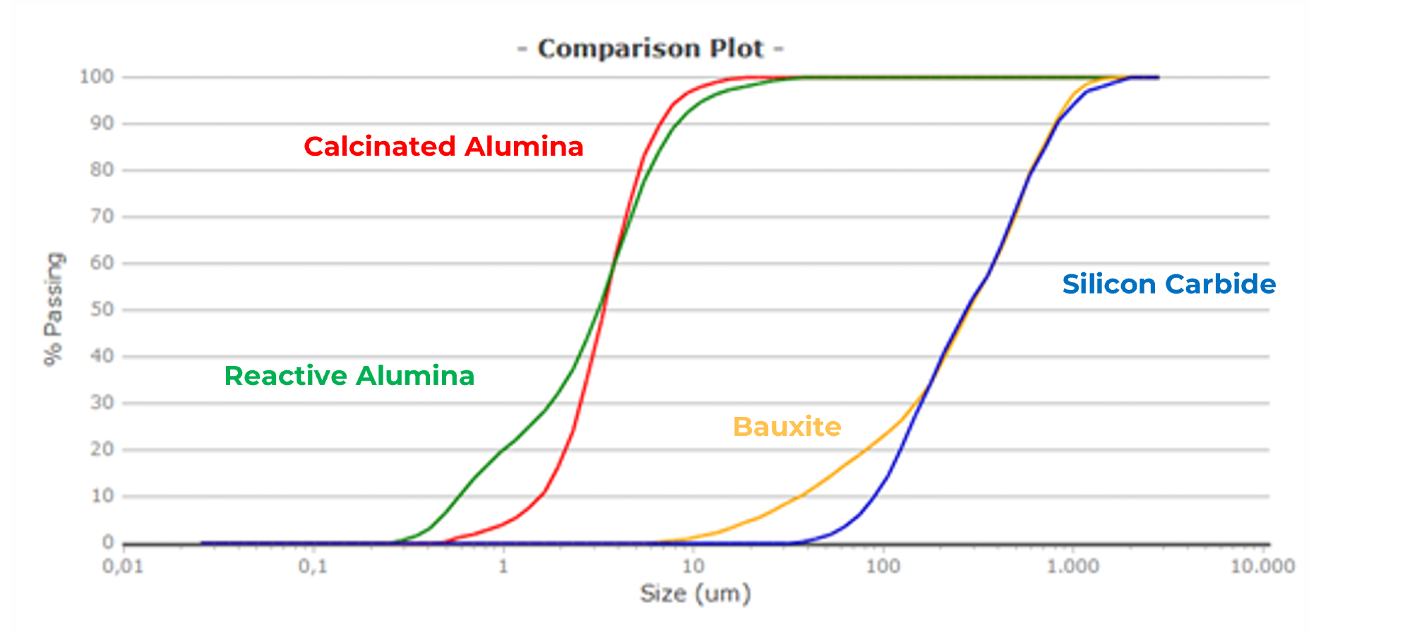
Figure 3. Comparison of the volume-based distributions (Q3) of four samples. Image Credit: Microtrac
Table 1. Percentiles (d10/d50/d90/d95). Source: Microtrac
| Id1: |
Calcinated Alumina |
Reactive Alumina |
Bauxite |
Silicon Carbide |
| 10 %tile [µm] |
1.56 |
0.575 |
35.47 |
89.61 |
| 50 %tile [µm] |
3.35 |
3.15 |
281.9 |
272.7 |
| 90 %tile [µm} |
6.59 |
8.11 |
796.6 |
819.6 |
| 95 %tile [µm] |
8.19 |
11.26 |
935.0 |
1038 |
Laser Diffraction analysis often has trouble recognizing large particles in a sample, so it is often combined with image analysis when dealing with broad particle size distributions. The example shows large particles in the bauxite and SiC samples, which augment and verify the laser diffraction measurement.
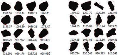
Figure 4. Oversized particles captured by the camera of the SYNC analyzer. Bauxite (left) and SiC (right). Particle size is below the images. Note that the largest particles are almost 1.5 mm. Image Credit: Microtrac
2. Porosity and Surface Area Characterization of Ceramic Extrudates for Catalytic Applications
The aforementioned ceramic extrudates play an important role in heterogeneous catalysis, especially in petrochemical processing, refinery operations, and environmental applications.
As well as their geometric qualities, critical design parameters such as surface area, porosity, surface chemistry, and cyclic stability must be carefully analyzed and verified.
Among these factors, porosity is extremely important in ceramic materials and must be carefully managed. Increasing porosity improves mass transfer and functional performance but reduces mechanical strength and structural robustness.
Low-porosity ceramics have a dense structure with minimal vacancies. This results in high mechanical strength and chemical durability, making them ideal for demanding situations such as catalyst supports under high pressure.
Their limited number of open channels, however, results in poor permeability and low thermal insulation. As a result, gas diffusion is restricted and heat is transferred rather than retained, reducing their effectiveness in applications that require mass transfer.
Contrastingly, high-porosity ceramics have a network of interconnected pores that promote gas transport and permeability. This is especially useful in catalytic extrudates, where reactants must efficiently reach active sites.
Increasing porosity, however, diminishes mechanical strength, making materials more prone to breaking during handling and operation. In addition, increased exposed surface area can marginally lessen chemical resistance.
To fully characterize surface area and porosity, a variety of analytical approaches are necessary. Common methods include gas adsorption and mercury intrusion porosimetry.
Each technique focuses on a certain pore size range and gives complementing data, adding to a comprehensive understanding of the surface area and pore structure.
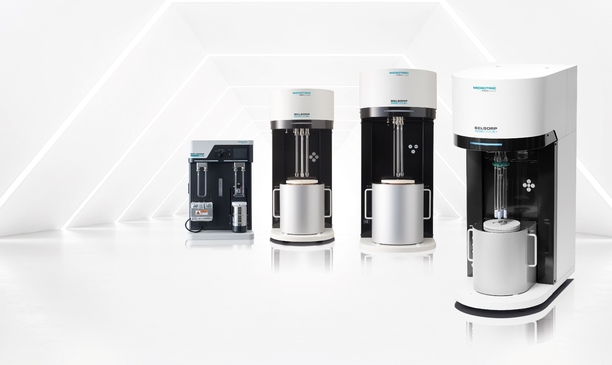
A selection of MICROTRAC gas adsorption analyzers: BELSORP MAX G, BELSORP MAX X, BELSORP MINI X, BELSORP MR1. Image Credit: Microtrac
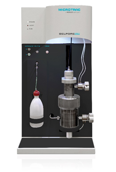
MICROTRAC’s BELPORE mercury porosimeter series for low-pressure (LP), medium-pressure (MP), and high-pressure (HP) reliably and reproducibly measures pore diameters from 1 mm to 3.6 nm. Image Credit: Microtrac
Gas adsorption analysis offers extensive information on specific surface area, pore volume, and pore size distribution from 0.35–500 nm.
These characteristics have a significant impact on the reactivity, sintering behavior, and overall functional performance of ceramics, particularly in catalysts, sensors, and filtration systems.
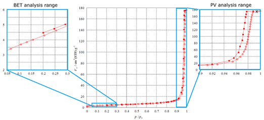
Figure 5. Nitrogen sorption isotherm of an alumina-based ceramic sample at 77 K, with annotations indicating the relevant evaluation ranges of the adsorption process. The BET region (relative pressure p/p0 = 0.05–0.30) is enlarged on the left, while the pore volume analysis range is enlarged on the right. The pore size distribution is derived from the full analysis range. Image Credit: Microtrac
The Brunauer-Emmett-Teller (BET) method (ISO 9277) is the most commonly used approach for calculating specific surface area (SSA). It measures the quantity of physiosorbed gas in both nonporous and micro- to macroporous substances.
The calculation uses the linearized BET plot to compute the monolayer capacity and the adsorbate molecule's cross-sectional area (0.162 nm2 for nitrogen). Using these factors, the SSA (m2/g) may be determined.
Pore volume (PV) can also be assessed. While PSD methods frequently provide information on associated pore volumes, the overall pore volume is typically calculated using Gurvich's approach.
This method translates the adsorbed amount at high relative pressure (usually p/p0 = 0.99), where the pores are believed to be filled by condensed adsorbate, into the total pore volume.
Finally, the pore size distribution (PSD) is an important part of material characterization. Micropores and mesopores have diverse adsorption properties, so they are often studied independently using various methodologies and models.
Traditionally, PSDs have been derived using both empirical and theoretical methodologies. Methods such as BJH, DH, CI, and INNES can be employed for mesoporous materials, each with their own set of assumptions, such as pore geometry.
Source: Microtrac
Results by the BJH method
(Harkins-Jura t-plot) |
Results by MIP
(SA model Cylindrical and Plate) |
| BET-SA 15.282 [m2 g-1] |
ap 15.597 [m2 g-1] |
Pore volume
(p/p0=0.9900) 0.2671 [cm3 g-1] |
Pore volume 0.2711 [cm3 g-1] |
|
Average pore diameter 69.53 [nm] |
Ceramic materials are often meso- to macroporous and frequently have hierarchical pore patterns, making mercury intrusion porosimetry (MIP) an essential characterization technique.
This method, detailed in ISO 15901-1, is based on driving non-wetting mercury into the pore system at an ambient temperature, by applying pressures of up to 414 MPa. The pore width ranges from roughly 1000 µm to 3.6 nm. The Washburn equation states that the pore diameter is inversely proportional to the applied pressure (d = (4γ cos θ) / p).
The volume of intruded mercury, as determined simultaneously by capacitance measurement, is proportional to the material's accessible pore volume.
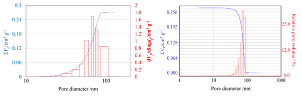
Figure 6. Pore size distribution calculation based on gas adsorption analysis (left) and mercury intrusion porosimetry (right). Image Credit: Microtrac
Table 2. Comparison of pore size distribution and porosity analysis by gas adsorption and mercury intrusion porosimetry. Source: Microtrac
Results by BJH method
(Harkins-Jura t-plot) |
Results by MIP
(SA model Cylindrical and Plate) |
| Pore volume 0.2711 [cm3 g-1] |
Intra pore volume 0.2738 [cm3/g] |
| Surface Area 15.597 [m2 g-1] |
Intra-pore surface area 16.106 [m2/g] |
| Average pore diameter 69.53 [nm] |
Average pore diameter 68.0 [nm] |
Gas adsorption and mercury intrusion porosimetry (MIP) are only applicable within a specific pore size range. MIP is insufficient for the precise characterization of micropores due to accessibility and pressure constraints, while gas adsorption techniques become less reliable for bigger macropores.
The close agreement seen here suggests that the pore structure falls within the overlapping measurement ranges of both approaches.
The surface area and porosity of ceramic materials are extremely sensitive to synthesis, shape, and thermal treatment conditions, so accurate characterization is critical.
Characteristics such as raw materials, particle size, additives, and processing methods all have an impact on pore structure, connectivity, and, ultimately, material performance, with tiny alterations causing major differences.
Advanced analytical techniques, including gas adsorption and MIP, are critical for measuring these properties across the relevant pore size ranges. They offer a greater knowledge of process-structure connections by providing detailed information on surface area, pore volume, and pore size distribution, as well as focused optimization of ceramic materials for specific applications.
3. From Powders to Slurries: Controlling Dispersion
As powders turn into slurries, the emphasis switches from geometry to interaction. The way that particles behave in a liquid environment - whether they remain scattered or form aggregates - becomes equally as important as the particles' shapes.
NANOTRAC FLEX, which employs Dynamic Light Scattering (DLS), provides insight into nanoscale behavior. For example, during silica particle formation, DLS can measure particle growth in real time, displaying size evolution from roughly 178 nm to nearly 400 nm. These measurements closely match TEM data, indicating precision and the capacity to monitor operations as they occur.
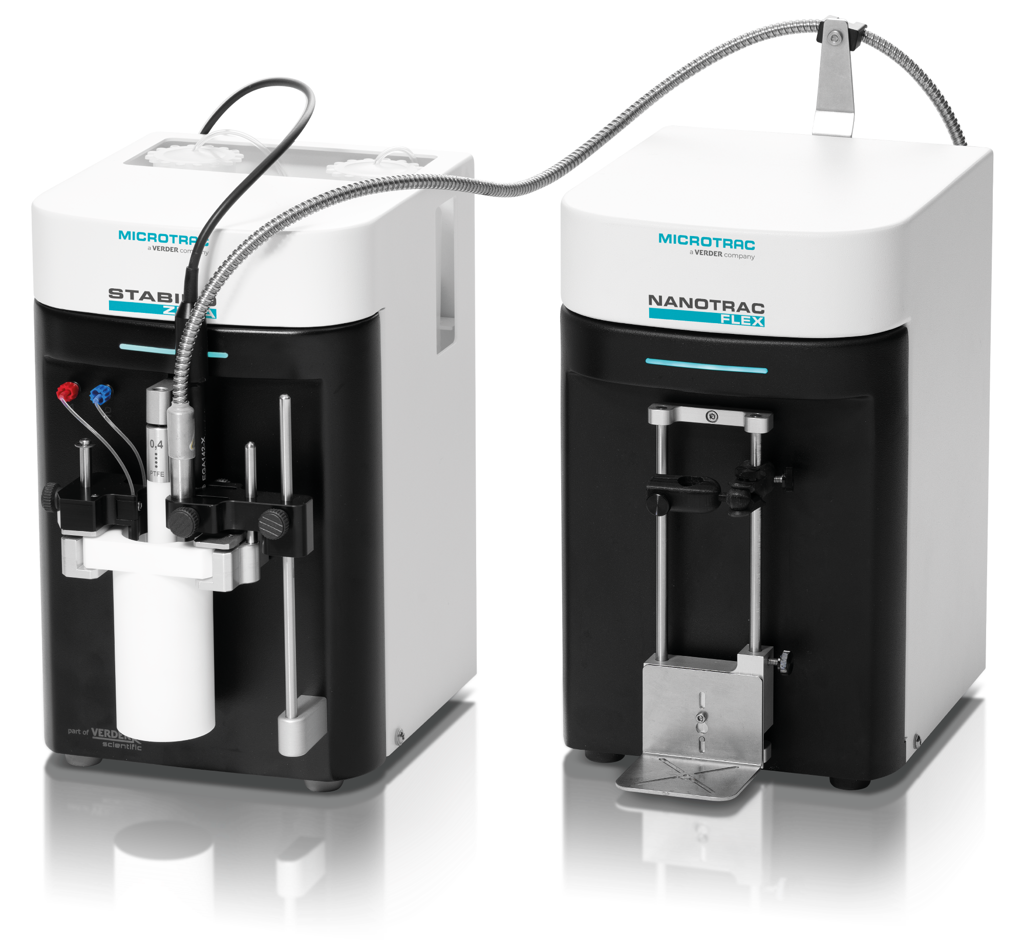
MICROTRAC’s NANOTRAC FLEX Nanoparticle Size Analyzer and STABINO ZETA Zeta Potential Analyzer. Image Credit: Microtrac
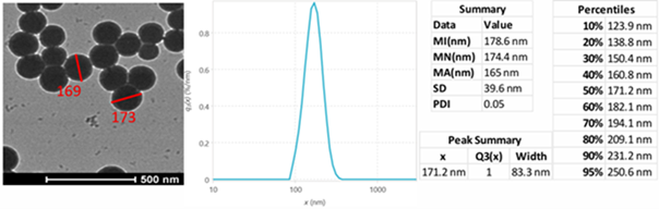
Figure 7. Precise measurements of various sizes of silica nanoparticles, validating the accuracy of Microtrac Flex dynamic light scattering (DLS) by comparison with Transmission Electron Microscope (TEM) data. In the DLS method, samples were measured conventionally by immersing the probe in the sample. Image Credit: Microtrac
This technique has the advantage of being able to measure a wide range of concentrations, from highly diluted solutions to industrially relevant suspensions. This reduces the need for unnecessary dilution, allowing measurements to reflect actual processing conditions.
While particle size is useful information, it does not entirely explain stability: particle charge has an equally essential role.
Zeta Potential measurements show how particles interact, revealing stable regions and predicting aggregation behavior. In alumina dispersions, for example, coagulation begins before the isoelectric point is achieved, demonstrating that instability can arise long before complete charge neutralization.
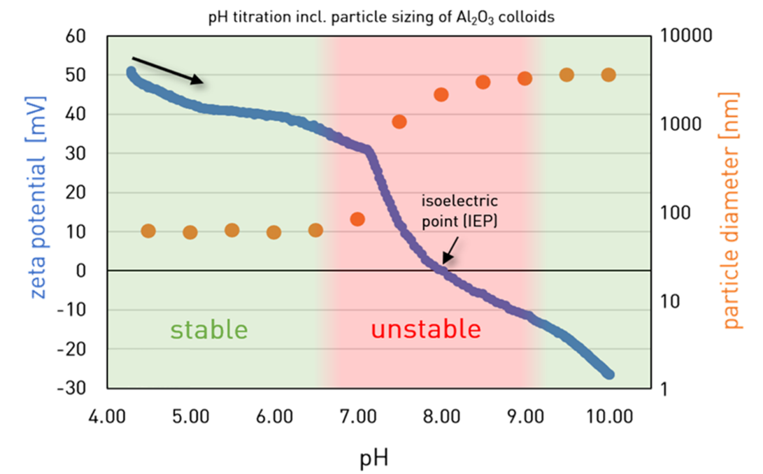
Figure 8. Blue curve: Fast particle charge titration of an alumina dispersion with NaOH. Orange curve: Simultaneous size [nm] measurements. Image Credit: Microtrac
Combining size and charge measurements allows users to detect the onset of aggregation and improve formulations accordingly. Polyelectrolyte titrations improve this capability by determining the crucial point at which dispersion begins to break down.
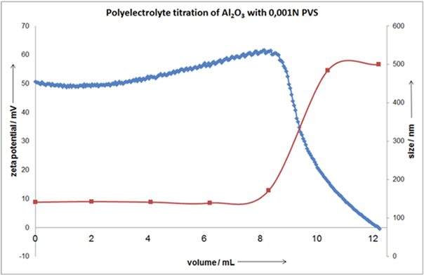
Figure 9. Polyelectrolyte titration with simultaneous size measurement. Image Credit: Microtrac
This combination method turns slurry formulation into a controlled, data-driven process, allowing for faster optimization and improved consistency.
4. From Stability to Usability: Sedimentation and Redispersion
Even a well-dispersed slurry and strong particle-particle repulsion are not necessarily stable. Most ceramic suspensions will undergo sedimentation with time, resulting in phase separation and performance changes. However, stability is not the only factor that determines usability: a formulation must also be redispersible.
TURBISCAN technology allows for early detection of instability by scanning the sample's height and tracking variations in backscattering over time. This method detects sediment production at the bottom and clarification at the top, before these changes become noticeable.
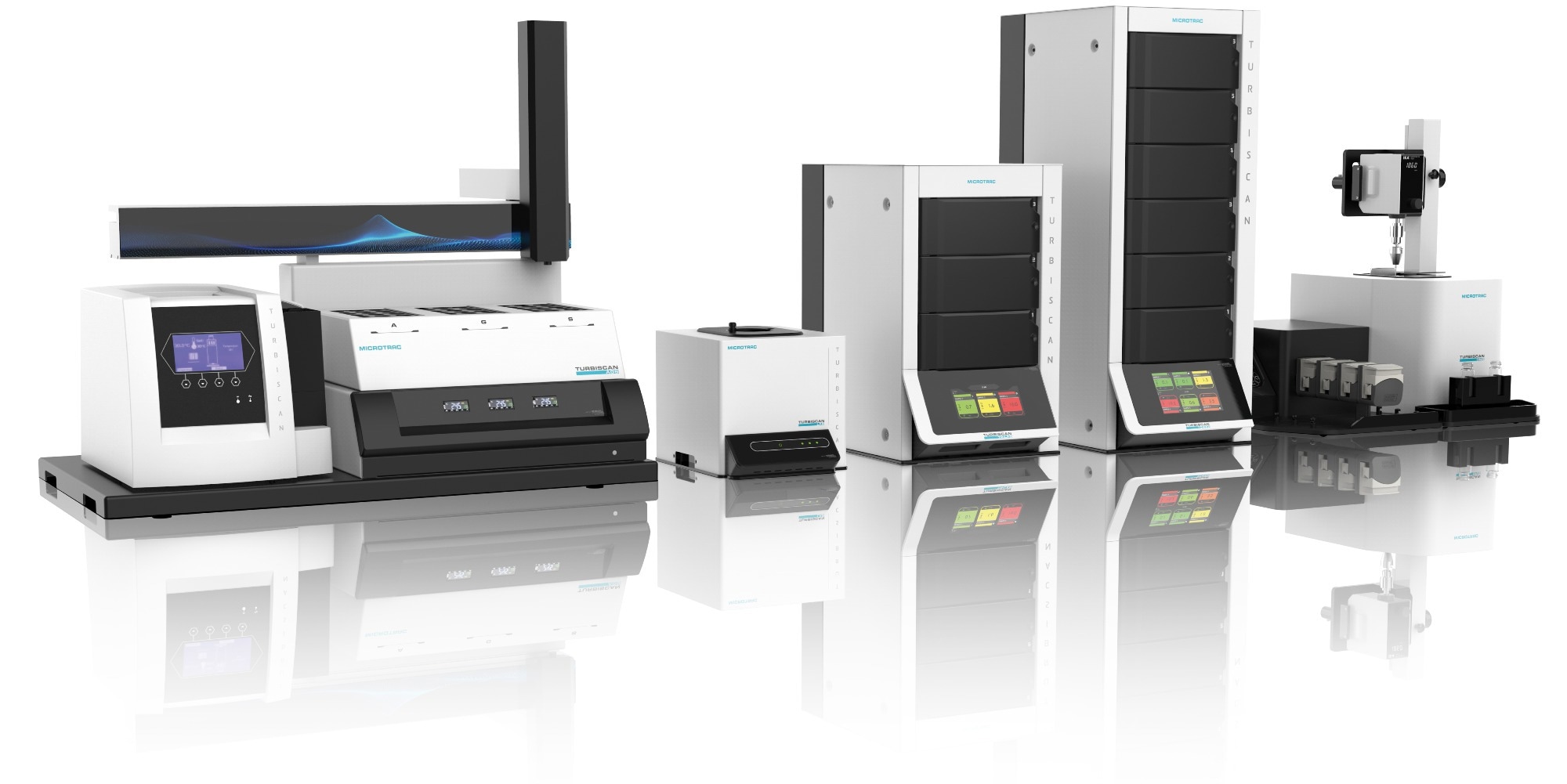
MICROTRAC’s TURBISCAN range for Stability, Shelf-Life, and Dispersibility Analysis. Image Credit: Microtrac
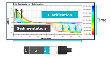
Figure 10. Sedimentation graph with TURBISCAN. Image Credit: Microtrac
To facilitate easy comparison between formulations, the Turbiscan Stability Index (TSI) gives a single numeric value that reflects overall destabilization. This enables the rapid ranking of samples, frequently within hours.
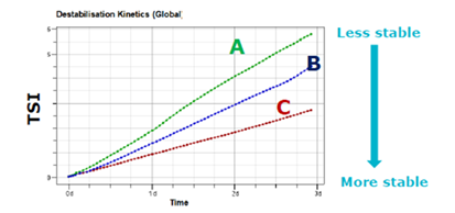
Figure 11. TSI kinetics over three days. Image Credit: Microtrac
Beyond ranking, the approach provides precise information about sediment structure and kinetics. Sediment thickness, compactness, and settling velocity are all factors that contribute to a system's instability.
Following this, the most important practical question is whether the system can be restored. Redispersibility studies determine how well a formulation recovers to its original state under controlled mixing.
The completeness and speed of redispersion can be assessed by comparing the recovered backscattering signal to the initial state.
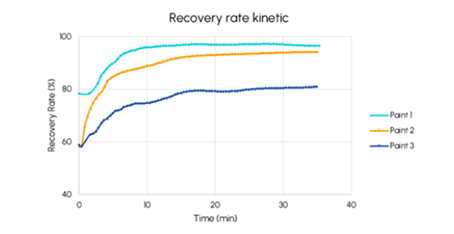
Figure 12. Recovery rate (%) as a function of time (minutes) for three paints. Image Credit: Microtrac
This is especially relevant in ceramic inks: clear dfferences can be seen when comparing three formulations with similar pigments but different solutions. One formulation has low sedimentation and good redispersibility, whereas another settles quickly and cannot be completely restored. Viscosity is important here, as more viscosity slows sedimentation but does not guarantee redispersibility.
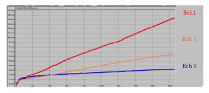
Figure 13: Comparison of sedimentation kinetics between three samples. Image Credit: Microtrac
Conclusion
Particle behavior ultimately governs performance throughout the ceramic production chain, from powders to suspensions. Combining complementary characterization techniques allows users to connect size, shape, interaction, and stability into a single cohesive understanding.
Rather than depending on measurements in isolation, this integrated approach establishes a continuous link between raw materials, processing conditions, and ultimate product performance.
It enables manufacturers to detect issues earlier, optimize formulations more efficiently, and ensure consistent quality in increasingly complex ceramic systems.
In this way, particle characterization transitions from a supporting analytical step to a primary instrument for innovation, facilitating measurement and, importantly, genuine control over material behavior.

This information has been sourced, reviewed, and adapted from materials provided by Microtrac.
For more information on this source, please visit Microtrac.