Feb 20 2006
Elizaveta Galitckaia / Shutterstock
Generally, when one thinks about microscopes, electron or optical microscopes will come to mind. Such microscopes produce a magnified image of an object by directing electromagnetic radiation, such as electrons or photons, on its surface.
Electron and optical microscopes can effortlessly produce two-dimensional magnified images of the surface of an object, with a magnification as large as 1000X for an optical microscope, and as large as 100,000X for an electron microscope.
Although these microscopes are robust tools, the images acquired are normally in the plane horizontal to the object’s surface. Such microscopes do not directly supply the vertical dimensions of the surface of an object or the depth and height of the surface features.
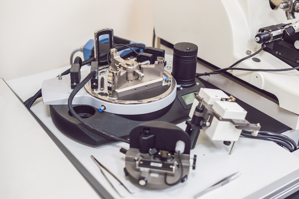
The atomic force microscope (AFM), built in the mid-1980s, uses a sharp probe to enlarge surface features. The AFM makes it possible to image the surface topography of an object with very high magnifications, up to 1,000,000X.
The AFM’s magnification is made in three dimensions, the horizontal X-Y plane, and the vertical Z dimension. Binnig and Rohrer, the inventors of the tunneling microscope, agree that such a robust method has its roots in the stylus profiler.
Stylus Profilers
Magnification of the object’s vertical surface features—that is, those features arising from the horizontal plane and spreading in the vertical direction—has traditionally been measured by a stylus profiler.
Invented by Schmalz in 1929, this profiler utilized an optical lever arm to track the motion of a sharp probe positioned at the end of a cantilever. A magnified profile of the surface was produced by recording the stylus motion on a photographic paper. This type of “microscope” produced profile “images” with a magnification of >1000X.
A typical issue with stylus profilers was the potential bending of the probe from collisions with surface features. Such “probe bending” was due to horizontal forces on the probe caused when the probe came across large features on the surface. This issue was first looked at by Becker in 1950 and later by Lee.
Becker and Lee proposed that the probe can be oscillated from a null position above the surface to make contact with the surface. Becker stated that when this vibrating profile technique is used for measuring images, the detail of the images would be determined by the probe’s sharpness.
In 1971, Russell Young built a non-contact type of stylus profiler called the topographiner. He used the fact that the electron field emission current between a surface and a sharp metal probe largely depends on the distance of the probe sample for electrically conductive samples.
The probe in the topographiner was directly mounted on a piezoelectric ceramic used to shift the probe in a vertical direction above the surface. An electronic feedback circuit tracking the electron emission was then used to shift the piezoceramic, and thus keep the probe sample spacing secured.
Then, with piezoelectric ceramics, the probe was used to scan the surface in the horizontal (X-Y) dimensions. By tracking the X-Y and Z position of the probe, a 3D image of the surface was created. The resolution of Young’s instrument was regulated by the vibrations of the instruments.
Scanning Tunneling Microscopes and Atomic Force Microscopes
In 1981, IBM scientists were able to utilize the techniques initially shown by Young to create the scanning tunneling microscope (STM). Binnig and Rohrer showed that by regulating the vibrations of an instrument, which was quite similar to Young’s topographiner, the electron tunneling current between a sample and a sharp probe can be tracked.
Since electron tunneling is relatively more sensitive than field emissions, the probe could be used to scan very near the surface. The results were amazing; Binnig and Rohrer could see separate silicon atoms on a surface. Although the STM was thought to be fundamental progress for scientific research, it had few applications, as it worked only on electrically conductive samples.
Profilers underwent a major development in 1986 when Binnig and Quate demonstrated the AFM. Using an ultra-small probe tip at the end of a cantilever, the AFM could attain very high resolutions.
At first, the cantilever’s motion was tracked with an STM tip. However, it was soon understood that a light-lever, close to the technique initially employed by Schmalz, could be used for quantifying the motion of the cantilever. In their paper, Binnig and Quate suggested that the AFM could be enhanced by vibrating the cantilever above the surface.
In 1987, Wickramasinghe provided the first practical demonstration of the vibrating cantilever technique in an AFM. He used an optical interferometer to calculate the amplitude of a cantilever’s vibration.
Using this optical method, oscillation amplitudes between 0.3 nm and 100 nm were realized. Upon each oscillation, the probe comes into close contact with the surface, and Wickramasinghe was able to detect the materials on a surface. The variances between photo-resist and silicon were easily observed.